


Hardware components | ||||||
 |
| × | 1 | |||
 |
| × | 1 | |||
 |
| × | 1 | |||
Software apps and online services | ||||||
 |
| |||||
Hand tools and fabrication machines | ||||||
 |
| |||||
(direct PWM control, no libraries needed, any MCU)
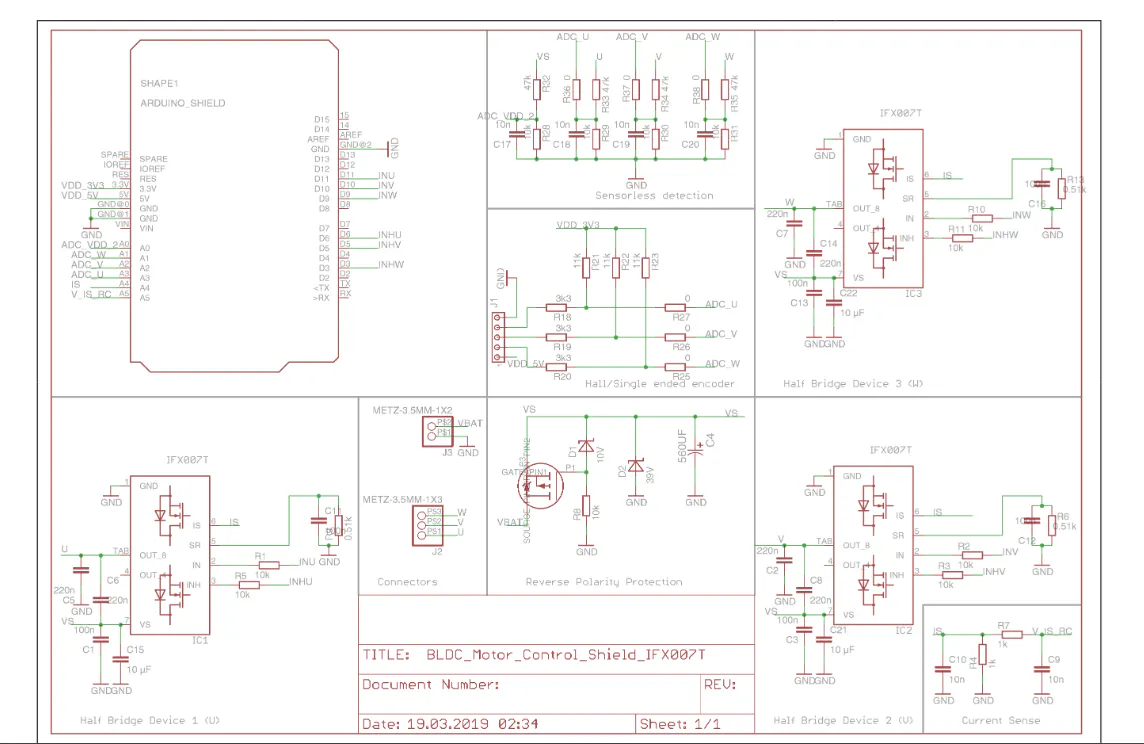
The Infineon IFX007T is a robust motor driver IC designed for automotive and industrial applications. Each IC contains a protected half‑bridge consisting of a P‑MOS high‑side transistor and an N‑MOS low‑side transistor. By combining two IFX007T ICs, a full H‑bridge can be built, which allows a brushed DC motor to be driven in both directions, Combining a p-channel high-side MOSFET and an n-channel low-side MOSFET with a built-in driver IC in a single package. Thanks to the p-channel high-side switch, no charge pump is required, which helps reduce EMI.
The integrated driver IC simplifies microcontroller interfacing by offering
- Logic-level inputs
- Diagnostic features with current sensing
- Adjustable slew rate
- Dead-time generation
- Comprehensive built in protection against over temperature, under voltage, over current, and short circuits
In this project, 2 IFX007T ICs (U channel and V channel) out of 3 of the Motor Control Shield are used to drive a 775 brushed DC motor, powered by a 12V drill battery pack.
Control is provided by an Arduino‑compatible Adafruit Feather nRF52840 Express board for 3.3V logic level PWM and GPIO signals. As a matter of fact, any MCU will be able to drive these motor control ICs.
The project demonstrates speed control using PWM duty cycle and direction control using polarity switching, with LEDs providing visual feedback.
DemoHere is the video demo of speed and direction control with a DC drill machine
Theory of OperationEach IFX007T half‑bridge can connect a motor terminal either to the supply voltage or to ground.
When two ICs are combined, one can drive the motor terminal high while the other drives the opposite terminal low, creating a full H‑bridge. For forward rotation, IC1’s P‑MOS connects motor terminal A to +12V while IC2’s N‑MOS connects motor terminal B to ground. For reverse rotation, IC2’s P‑MOS connects motor terminal B to +12V while IC1’s N‑MOS connects motor terminal A to ground.
- IN Pin of IFX007T takes logic level PWM from any Microcontroller
- INH Pin of IFX007T takes GPIO High or Low from Microcontroller
- VS Pin of IFX007T takes DC power supply (with High Current capability)
- Gnd is connected to both power ground and logic ground
Speed control is achieved by varying the PWM duty cycle applied to the active half‑bridge. A higher duty cycle increases the average voltage across the motor, resulting in faster rotation. The IFX007T includes built‑in dead‑time to prevent shoot‑through, as well as protection features such as overcurrent shutdown, thermal protection, and undervoltage lockout.
/*
  Project: Brushed DC Motor Control using IFX007T
  Hardware Setup:
    - Motor Driver: 2x Infineon IFX007T ICs (each configured as a half-bridge).
      Together they form a full H-bridge for driving a 775 brushed DC motor.
    - Microcontroller: Adafruit Feather nRF52840 Express (Arduino-compatible).
    - Power Source: 12V drill machine battery pack.
    - Inputs:
        * MOTOR_MODE_BUTTON (mode select: stop/forward/reverse)
        * MOTOR_SPD_UP_BUTTON (increase speed)
        * MOTOR_SPD_DOWN_BUTTON (decrease speed)
    - Outputs:
        * LEDs for feedback (mode, speed up/down, forward, reverse, stop).
        * PWM signals to IFX007T ICs for motor control.

  Operation:
    - Speed control is achieved by varying PWM duty cycle.
    - Direction control is achieved by enabling one half-bridge path at a time:
        * Forward: IC1 P-MOS ON (motor terminal A = +12V), IC2 N-MOS ON (motor terminal B = GND).
        * Reverse: IC2 P-MOS ON (motor terminal B = +12V), IC1 N-MOS ON (motor terminal A = GND).
    - Dead-time and built-in protection in IFX007T prevent shoot-through.
    - Offset duty cycle ensures motor startup torque and avoids stall.


*/The hardware consists of two IFX007T ICs configured as half‑bridges, an Adafruit Feather nRF52840 Express microcontroller, a 775 brushed DC motor, and a 12V drill battery pack as the power source. Three buttons are used as inputs: one for mode selection (stop, forward, reverse), one for speed increase, and one for speed decrease. LEDs are used as outputs to provide feedback for mode changes and speed adjustments. The microcontroller generates PWM signals that drive the IFX007T ICs, enabling speed and direction control.
The code sets up an Arduino‑compatible Feather board to control a brushed DC motor through two IFX007T half‑bridge driver ICs. It defines pins for three buttons and several LEDs, then uses those inputs to change the motor’s operating mode and adjust speed. Pressing the mode button cycles between stop, forward, and reverse states; in stop mode the driver is disabled and PWM outputs are set to zero, while in forward or reverse mode the driver is enabled and one half‑bridge is activated to set motor polarity. The speed‑up and speed‑down buttons adjust duty cycle values (speed_U for forward, speed_V for reverse), which are applied to the PWM outputs with a fixed offset to ensure the motor has enough torque to start. LEDs provide visual feedback: one blinks in stop mode, another blinks in forward mode, and a third blinks in reverse mode, while additional LEDs flash briefly when buttons are pressed. In summary, the program reads button inputs, updates mode and speed variables, drives the IFX007T ICs with PWM signals to control motor direction and speed, and uses LEDs to indicate system status.
In Summery :
- Microcontroller's one GPIO drives both (INHU+INHV) together LOW to disable the motor Drive or stop from running, while driven HIGH, the motor is allowed to run
- Microcontroller's PWM1 Drives INU pin while INV is grounded to achieve Clockwise rotation, speed is adjusted with the duty cycle of PWM1
- Microcontroller's PWM2 Drives INV pin while INU is grounded to achieve Counter Clockwise rotation, speed is adjusted with the duty cycle of PWM2
// ----------- Speed Up Button pressed -----------
if (digitalRead(MOTOR_SPD_UP_BUTTON) == LOW) {
  // Forward mode
  if (MODE == 1 || MODE == 2) {
    speed_V = 0; // disable reverse
    if (speed_U < 180) speed_U += 5;
    analogWrite(MOTOR_PWM_DRIVER_CCW, speed_V);           // IC2 off
    analogWrite(MOTOR_PWM_DRIVER_CW, speed_U + offset);   // IC1 PWM → forward
  }

  // Reverse mode
  if (MODE == 4 || MODE == 5) {
    speed_U = 0; // disable forward
    if (speed_V < 180) speed_V += 5;
    analogWrite(MOTOR_PWM_DRIVER_CW, speed_U);            // IC1 off
    analogWrite(MOTOR_PWM_DRIVER_CCW, speed_V + offset);  // IC2 PWM → reverse
  }
}

// ----------- Speed Down Button pressed -----------
if (digitalRead(MOTOR_SPD_DOWN_BUTTON) == LOW) {
  // Forward mode
  if (MODE == 1 || MODE == 2) {
    speed_V = 0;
    if (speed_U >= 5) speed_U -= 5;
    analogWrite(MOTOR_PWM_DRIVER_CCW, speed_V);           // IC2 off
    analogWrite(MOTOR_PWM_DRIVER_CW, speed_U + offset);   // IC1 PWM reduced
  }

  // Reverse mode
  if (MODE == 4 || MODE == 5) {
    speed_U = 0;
    if (speed_V >= 5) speed_V -= 5;
    analogWrite(MOTOR_PWM_DRIVER_CW, speed_U);            // IC1 off
    analogWrite(MOTOR_PWM_DRIVER_CCW, speed_V + offset);  // IC2 PWM reduced
  }
}When a button is pressed, the code checks the current mode (MODE).
- In forward mode, only
speed_Uis active. IC1 (CW driver) gets PWM, IC2 (CCW driver) is grounded by active lowing it with internal N-MOS. - In reverse mode, only
speed_Vis active. IC2 (CCW driver) gets PWM, IC1 (CW driver) is grounded by active lowing it with internal N-MOS. - The
offsetensures the motor always has enough torque to start. - The
analogWritecalls are the actual commands that flip polarity and adjust motor speed. - When the motor needs to be stopped, the INHU and INHV pins are made LOW which disables both IC1 and IC2 ignoring any input to INU and INV pins.
Driving a large brushed DC motor like the 775 can generate significant heat in the driver ICs. The IFX007T mitigates this with low Rds(on) MOSFETs to reduce conduction losses, overtemperature shutdown to protect against overheating, and overcurrent protection to prevent damage during stalls. Good PCB layout and heat sinking are recommended for continuous operation under heavy load.
One interesting application may be Regenerative Breaking, which can stop the motor very fast by using the freewheeling of load (drill chuck) to turn the motor into a DC generator and convert the mechanical power into electrical energy to charge up the battery for a moment.
Another interesting way to break the motor is to enable both Channel U and V together to short the motor through the MOSFETs of IFX007T to perform Electronic Breaking, although this may damage the ICs if the generated freewheeling current is very high.
ConclusionThis project demonstrates how two IFX007T ICs can be combined into a full H‑bridge to control a brushed DC motor. By using PWM duty cycle for speed control and polarity switching for direction control, reliable motor operation is achieved. The built‑in protection features of the IFX007T make it a safe and efficient choice for motor control applications.


Comments