///////////// Header Files ////////////////
#include <SPI.h>
#include "epd1in54.h"
#include "epdif.h"
#include "epdpaint.h"
#include <RTC.h>
#include <DeviceControlXMC.h>
#include "epdpaint.h"
//////////// Class /////////////
XMCClass xmc2go;
RTCClass rtc;
//////////// Variables /////////
int COLORED = 0; // White in Black
int UNCOLORED = 1; // Black in White
int pos = 20;
uint32_t sleep = 1;
uint32_t temperature = 0;
int pwm = 200;
size_t free_memory;
unsigned char image[8196];
/////////// Enum ///////////////
// width must be multiple of 8//
Paint paint(image, 0, 0);
Epd epd;
//////// I/O pin mapping ////////
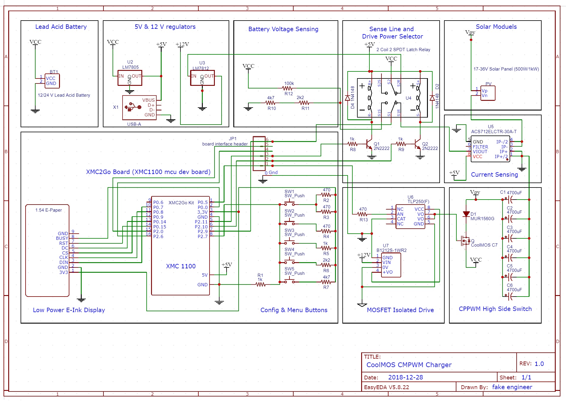
#define ADC_PB A1 // 5 push buttons on adc1
#define ADC_SL A0 // voltage and current sense on adc0
#define PWM_GD 8 // pwm gate drive
#define SEL_VS 11 // relay coil trigger to switch voltage sensing
#define SEL_CS 10 // relay coil trigger to switch current sensing
//////////////////////////////////////////////////////
void setup()
{
flush_epd();
initIO();
///// Init Full Display Update ///////////
if (epd.Init(lut_full_update) != 0)
{return;}
///// Init Partial Display Update ////////
if (epd.Init(lut_partial_update) != 0)
{return;}
////////// Clears Up Full Disp ///////////
// bit set = white, bit reset = black
epd.ClearFrameMemory(0xFF);
epd.DisplayFrame();
epd.ClearFrameMemory(0xFF);
epd.DisplayFrame();
rtc.begin();
xmc2go.configureSleepMode(DEEP_SLEEP_MODE,USIC_OFF ,LEDT_OFF,CCU_OFF,WDT_OFF,FLASH_OFF);
// active 7.62mA sleep 1.80mA
// FLASH_ON takes extra 0.55mA
rtc.setTime(0, 0, 0); // hrs, min, sec
rtc.setDate(0, 0, 0); // day, mon, yrs
rtc.setAlarmTime(0, 0, 1); // 1 sec alarm wakes from sleep
rtc.enableAlarm(rtc.ALARM);
rtc.attachInterrupt(alarmMatch);
}////////////////// Void Setup Ends//////////////
/////////////////////////////////////////////////
/////////////////////////////////////////////////
void loop()
{
int adc0 = analogRead(A0);
int adc1 = analogRead(A1);
char VAL[4];
free_memory = xmc2go.freeRAM_Heap();
temperature = xmc2go.getTemperature();
// Set Active Area on Disp with Orientation and Color //
// more RAM allows more disp area to be used at once
paint.SetWidth(200);
paint.SetHeight(200);
paint.SetRotate(ROTATE_270);
paint.Clear(UNCOLORED);
if(/*pwm<=250 && `*/ adc1>150 && adc1<190)
{
//pwm=pwm+5;
//analogWrite(PWM_GD,pwm);
digitalWrite(8,HIGH);
}
if(/*pwm>=5 && */ adc1>300 && adc1<340)
{
// pwm=pwm-5;
// analogWrite(PWM_GD,pwm);
digitalWrite(8,LOW);
}
if(adc1>490 && adc1<530)
{
digitalWrite(10,HIGH);
delay(150);
digitalWrite(10,LOW);
}
if(adc1>680 && adc1<720)
{
digitalWrite(11,HIGH);
delay(150);
digitalWrite(11,LOW);
}
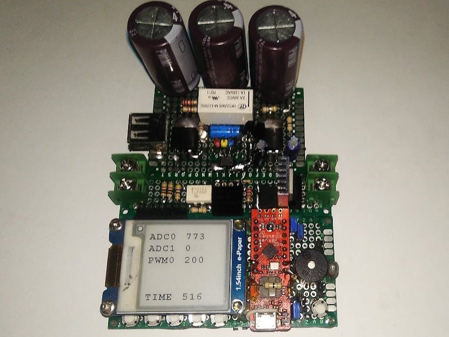
paint.DrawStringAt(10,20, "ADC0", &Font24, COLORED);
paint.DrawStringAt(10,50, "ADC1", &Font24, COLORED);
paint.DrawStringAt(10,80, "PWM0", &Font24, COLORED);
// paint.DrawStringAt(10,110, "SCNT", &Font24, COLORED);
// paint.DrawStringAt(10,140, "FRAM", &Font24, COLORED);
paint.DrawStringAt(10,170, "TIME", &Font24, COLORED);
paint.DrawStringAt(100,20, itoa(adc0,VAL,10), &Font24, COLORED);
paint.DrawStringAt(100,50, itoa(adc1,VAL,10), &Font24, COLORED);
paint.DrawStringAt(100,80, itoa(pwm,VAL,10), &Font24, COLORED);
// paint.DrawStringAt(100,110, itoa(sleep,VAL,10), &Font24, COLORED);
// paint.DrawStringAt(100,140, itoa(free_memory,VAL,10), &Font24, COLORED);
paint.DrawStringAt(100,170, itoa(millis()/1000,VAL,10), &Font24, COLORED);
////////////////////////////////////////////////////////////////////////////////
epd.SetFrameMemory(paint.GetImage(), 0, 0, paint.GetWidth(), paint.GetHeight());
epd.DisplayFrame();
/////////////////////////////////////////////////////
// xmc2go.enterSleepMode(); // goes to sleep mode
// sleep++;
} ////////////////////// loop ends here /////////////
////////////////////////////////////////////////////
////////////////////////////////////////////////////
///////////////// Functions ////////////////////////////
// clean up dark spots on epaper display
void flush_epd (void)
{
if (epd.Init(lut_full_update) != 0)
{return;}
epd.ClearFrameMemory(0xFF);
epd.DisplayFrame();
epd.ClearFrameMemory(0xFF);
epd.DisplayFrame();
}
// alarm ISR
void alarmMatch()
{
xmc2go.enterActiveMode();
rtc.setTime(0, 0, 0); // hrs, min, sec
}
void initIO(void)
{
pinMode(10,OUTPUT);
pinMode(11,OUTPUT);
pinMode(8,OUTPUT);
digitalWrite(8,LOW);
digitalWrite(10,LOW);
digitalWrite(11,LOW);
}


_3u05Tpwasz.png?auto=compress%2Cformat&w=40&h=40&fit=fillmax&bg=fff&dpr=2)


Comments