


Hardware components | ||||||
 |
| × | 1 | |||
| × | 1 | ||||
| × | 1 | ||||
 |
| × | 1 | |||
| × | 1 | ||||
| × | 1 | ||||
| × | 1 | ||||
 |
| × | 1 | |||
| × | 1 | ||||
| × | 1 | ||||
| × | 1 | ||||
| × | 1 | ||||
Software apps and online services | ||||||
| ||||||
 |
| |||||
| ||||||
Hand tools and fabrication machines | ||||||
 |
| |||||
🐁🐁🐁🐁🐁🐁
This Mouse Trap project is an Arduino Uno Q–based prototype designed to detect and capture mouse without killing them. A camera monitors the inside of the trap, while an AI model identifies when a mouse has entered.
After a mouse is detected, a servo activates the trap mechanism and releases the spring, closing the trap. The capture status is then shown through a Web UI available on the local network. When internet access is available, the device also sends a notification through the Pushover IoT service.
Features of This SolutionI intend to implement following features for this solution :-
- Uses AI Camera to Detect Mouse or Rat trying to steal food
- Mouse is Captured based on Electronic Trap Activation Mechanism
- Mouse can be seen on Web UI
- IoT notification will be send to User if they are away from Home
While the aim of this project is to prototype a futuristic rodent control product, this idea can be expanded into capturing wild animals and underwater fish/aquatic specie sample collection for research and scientific works.
Quick DemoNote: This project is a prototype. The mechanical trap must be tested carefully to ensure that it captures mice safely and does not cause injury.
This prototype is tested exclusively with a toy mouse or other non-living test object. No live animals are used during development or testing.
The trap mechanism should still be operated carefully because the servo, spring, and moving parts may cause injury or equipment damage.
Trap Camera's VideoFeed
External View
Pushover Notification on Android
The camera continuously provides frames to the AI detection system. Each frame is analyzed for the presence of a mouse. When the detection confidence reaches the configured threshold, the application checks whether the trap is armed and has not already been triggered.
The complete process is:
- The camera captures a frame.
- The AI model analyzes the frame.
- The application checks for a mouse detection.
- The confidence score is compared with the configured threshold.
- The trap state is checked.
- The servo activates the closing mechanism.
- The trap state changes to triggered or captured.
- The event is displayed in the Web UI.
- A Pushover notification is sent if an internet connection is available.
A software state (while forever lockup loop !) variable prevents repeated detection from activating the servo multiple times during the same capture event.
System Level Block DiagramThe infographic below illustrates how all the pieces fit together:
The hardware will be build around Arduino Uno Q 4 GB which comes with Qualcomm Dragonwing QRB2210 microprocessor, which is the quad-core 2.0 GHz CPU, Adreno GPU and can run full Debian Linux Desktop, hosting webUI, python, network connectivity
The STM32U585Arm® Cortex®-M33 microcontroller core running at 160 MHz will handle the embedded hardware part like user proximity detection, servo control, status indication, enable/activation input.
Following hardware will be needed to develop this prototype:
- Arduino® UNO Q
- USB-C® hub adapter with external power, if required for the camera
- Optional Cooling Fan
- USB camera or compatible camera module
- Servo motor suitable for the trap mechanism
- Suitable power supply and Ca for the Arduino Uno Q and servo
- Computer or smartphone with network access
- Mechanical mouse entrapment/prison style live capture trap
- Toy Mouse for Demonstration
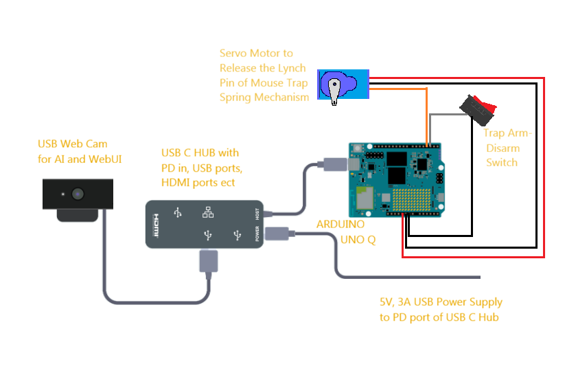
The camera is mounted in a position that provides a clear view of both the trap entrance and its interior, and it is connected to the Arduino Uno Q. The servo is attached to the trap’s release or closing mechanism, with its control wire connected to the configured GPIO pin.
- Pin D3 is used to => control the servo
- Pin D2 is to => arm/disarm the trap with a switch
- Onboard LED 3 and LED 4's RED LEDs => indicate Armed status
- Onboard LED 3 and LED 4's GREEN LEDs => indicate Disarmed status
Where required by the camera setup, a powered USB-C hub is used. The USB C hub is powered by a 20 Watt UGreen Charger capable of delivering 5V, 3A. A very high quality USB C power cable is used to deliver solid power
The camera, servo, trap, and associated wiring are securely fixed to prevent unintended movement of any component.
The Arduino Uno Q and all connected hardware are then powered on. Before the trap is put into use, the mechanism is tested without an animal present, with particular attention given to the servo position, spring tension, and the manner in which the trap closes.
Software/Web Services OverviewYou may need to create account/login/download following software/apps/web services to replicate this project:
- Arduino App Lab 0.10.0 or latest
- Arduino Uno Q application (with C++, Python, HTML, CSS, JS codes)
- Pushover account, User Key (token), Application token
- Pushover app on Android/iOS/Desktop browser
- Edge Impulse Account
- AI model developed in Edge Impulse to detect Mouse
- Putty Terminal for SSH
NOTE: If you are starting with a brand new fresh Arduino Uno Q you may have to update App Lab, Debian Linux on Uno Q and other drivers/tools even before you can start working on any project !
See; Arduino Uno Q Official Documentations and Tutorials
ConfigurationThe following settings need to be configured before running the application:
- Training an AI model with images dataset (Edge Impulse)
- Camera input/video stream (Arduino Local IP)
- Mouse-detection confidence threshold (see Python code)
- Servo control pin (see C++ code)
- Servo position when the trap is ready (see C++ code)
- Servo position when the trap is triggered (C++ code)
- Trap reset and re-arm behavior (Python Code)
- Pushover application token (Python Code)
- Pushover user key (Python Code)
- Notification title and message (Pushover Web Account)
- Web UI port (Arduino Local IP)
Pushover credentials should not be committed to a public repository. A separate configuration file or environment-based configuration is recommended.
If you are trying to clone this project, please make your own Pushover Account here, it's free for 30 days, no payment required. After that 5$ one time purchase fee for lifetime license. You can basically try out the demo for free.
Creating an AI mouse detection model with Edge ImpulseStep 1: Create a Project
- Go to Edge Impulse Studio and create new account and log in.
- Click Create new project.
- Enter a suitable project name, such as Single Object Detection.
- Create the project.
Step 2: Upload the Images
- Go to Data acquisition.
- Click Upload data.
- Upload around 40 images of the object.
- Add the images to the training and testing datasets.
- Try to keep the lighting, background, and camera position consistent.
Step 3: Label the Objects
- Open the Labeling queue.
- Select an image.
- Draw a box around the object.
- Give the object a label, such as
object.
- Save the label and repeat this for every image.
- On the Image Tab Set Color Depth RBG and save parameter
Step 4: Create the Impulse
- Open Impulse design.
- Choose the image size, for example 320 × 320 pixels.
- Add the Image processing block.
- Add the Object detection (YOLO) learning block.
- Save the impulse.
Step 5: Generate Image Features
- Open the Image block.
- Click Generate features.
- Wait while Edge Impulse processes the images.
- Review the generated features to make sure the data looks correct.
Step 6: Train the YOLO Model
- Open the Object detection (YOLO) block.
- Select the required training settings.
- Set the number of training epochs, such as 100.
- Click Start training.
- Wait for the training process to complete.
Because the dataset contains only about 40 images, the model will work best under conditions similar to those used when collecting the images.
Edge Impulse AI model linkAlternatively, clone my project from this link, you don't need to go through all the steps then, just create/login to your Edge Impulse account and clone this :
https://studio.edgeimpulse.com/public/1103716/live
Linking Edge Impulse to Uno Q for Downloading AI modelsHere is the Official Edge Impulse Arduino Uno Q Guide and following is my short version of this official guide, you can follow anyone you wish.
To get the Edge Impulse AI model that is trained in Arduino Uno Q, we need to link Edge Impulse to Arduino Uno Q, then the trained AI models will show up in App Lab Interface to directly use in projects
1. Prepare the UNO Q in Arduino App Lab
- Open Arduino App Lab.
- Connect the UNO Q using a USB-C cable.
- Select and configure the UNO Q.
- Connect the board to Wi-Fi if you want to use remote login.
- Note the UNO Q IP address from App Lab.
2. Connect to the UNO Q using PuTTY
- Open PuTTY.
- Select SSH as the connection type.
Enter:
- Host Name: UNO Q IP address
- Port:
22 - Click Open.
- Log in with the Arduino Uno Q Linux username and password configured in App Lab (when the board was setup/updated first time)
3. Install Node.js and required software
Run the following commands in PuTTY:
sudo apt update
curl -sL https://deb.nodesource.com/setup_20.x | sudo bash -
sudo apt install -y gcc g++ make build-essential nodejs sox gstreamer1.0-tools gstreamer1.0-plugins-good gstreamer1.0-plugins-base gstreamer1.0-plugins-base-apps4. Install the Edge Impulse Linux CLI
Install the Edge Impulse Linux package globally:
sudo npm install edge-impulse-linux -g --unsafe-perm5. Connect a USB camera
- Connect a USB camera to the UNO Q through USB C Hub
- Make sure the device is detected by Linux.
- If device is not detected, power off and on the USB C Hub + Uno Q
- For a USB camera, you can check connected devices with:
ls /dev/video*You will see following response if camera is detected :
6. Connect the UNO Q to Edge Impulse
Run:
edge-impulse-linux- Follow the prompts shown in the PuTTY terminal.
- Sign in to your Edge Impulse account with e-mail and password
This part is done inside the putty terminal from Uno Q, where you provide your User ID and Password of your Edge Impulse account to link your Edge Impulse account to your Uno Q.
If this step is done correctly, your Edge Impulse AI models will show up in your app lab like this :
- Select or create an Edge Impulse project.
- Select the connected camera
- Allow the CLI to connect the UNO Q to your Edge Impulse project.
Step 1: Create a Pushover Account
Visit https://pushover.net/signup and create a new account using an email address and password. The login credentials should be retained for later use with the Android or iOS application.
A verification email will be sent to the registered email address. Follow the verification link, complete the account setup, and log in to Pushover.
Step 2: Download the Pushover App
Download the Pushover application on an Android or iOS device. After installation, log in using the email address and password associated with the newly created Pushover account.
Step 3: Name the Device
After logging in, assign a name to the device. The selected device name will appear in the Pushover account.
Device names are useful when multiple devices and projects are associated with the same account, particularly when notifications must be sent only to specific devices.
Step 4: Obtain the User Key and API Token
Log in to the Pushover account through a web browser.
Locate and copy the account’s Unique User Key. This alphanumeric string is unique to the account and will be required in the code.
Scroll down to the Your Devices section. Each device added to the account will be displayed in this section. For example, a device named Xiaomi_5 added through the Android application may be listed there.
Next, scroll down to the Your Applications section. An API token for an application can be created in this section. Each application can send up to 10, 000 messages per month.
Select Create an Application/API Token, enter a name for the application, accept the terms and conditions, and continue.
A unique API token will then be generated for the application. This alphanumeric string should be copied and stored securely, as it will be required for Python programming.
Important Summary
Two pieces of information are required from the Pushover account:
User Key string:  sdhf89weurfw9ur923jri34r03API
Token string: 394rwfh34r38r34t8wer84tjksfj
These two values allow hardware or software applications to communicate with the Pushover server and send notifications to the Pushover application.
Developing The Firmware on Arduino App LabThe firmware is developed on Arduino App Lab
Arduino App Lab for the Arduino Uno Q is an integrated development environment for creating and managing applications. It supports:
- C++ for developing firmware for the microcontroller
- Python for programming the microprocessor
- HTML, JavaScript, and CSS for designing web based user interfaces
- Video streaming, output data display and user input on Web UI
- Bricks (block based) programming for AI, machine learning and GUI design
- Libraries for interfacing with sensors, actuators, modules, and other external hardware
Overall, it is a sophisticated tool that brings all these capabilities together in one environment.
The left side contains the app’s navigation and file panels: My Apps is used to access personal projects, while Examples provides ready-made applications and Bricks provides reusable modules for functions such as web interfaces, sensors, storage, or AI. The highlighted project area contains the application’s files, including the Python program and the Arduino sketch. In the center, the editor displays the Linux-side Python code. On the Uno Q, Python runs on the Qualcomm/Linux processor, while the Arduino sketch runs on the STM32U585 microcontroller; the two sides can communicate through the Uno Q’s Bridge/RPC system. The controls across the top are used to select and connect to the Uno Q, and the Run button in the upper-right launches the app on the connected board. Thus, the marked areas together show App Lab’s main workflow: select a project, edit its Python or sketch files, connect to the Uno Q, and run an application that combines Linux-level features with real-time microcontroller control.
The firmware combines C++ code running on the Arduino microcontroller with Python code responsible for AI processing, user-interface communication, and IoT notifications. The C++ layer controls the physical hardware, including the activation button, servo motor, and status LEDs. The Python layer processes the camera stream, identifies objects, determines whether a mouse has entered the trap, and sends commands back to the microcontroller.
Communication between both layers is handled through the Arduino Router Bridge. This arrangement separates hardware control from high-level AI processing while allowing both programs to operate as a single automated mouse-trap system.
Bricks, Libraries and Bridges
To use Bricks and Libraries in project code, appropriate Bricks and Libraries need to be added to the active project as follows :
Searching Bricks:
Adding Bricks:
Searching Libraries:
Adding Libraries:
The Python application uses Arduino application bricks to provide ready-made functionality for the web interface and computer-vision system:
from arduino.app_utils import App, Bridgefrom arduino.app_bricks.web_ui import WebUIfrom arduino.app_bricks.video_objectdetection import VideoObjectDetection- The
WebUIbrick manages communication between the Python application and the browser-based interface. - The
VideoObjectDetectionbrick processes the camera stream and returns detected objects together with their confidence values.
ui = WebUI()
detection_stream = VideoObjectDetection(    confidence=0.5,    debounce_sec=0.0)
The detection confidence is initially set to 0.5, meaning that detections with a confidence value of at least 50 percent can be reported by the object-detection system. A web-interface message can also modify the threshold during runtime:
ui.on_message( "override_th", lambda sid, threshold: detection_stream.override_threshold(threshold))The C++ program includes the Router Bridge library:
#include <Arduino_RouterBridge.h>The bridge is initialized inside setup():
Bridge.begin();Specific C++ functions are then made available to Python:
Bridge.provide(    "mouse_trap_enabled",    mouse_trap_enabled);
Bridge.provide(    "drive_trap_activation_servo",    drive_trap_activation_servo);
Bridge.provide(    "reset_trap_activation_servo",    reset_trap_activation_servo);
These declarations create callable bridge functions. Python invokes them with Bridge.call():
if Bridge.call("mouse_trap_enabled"): Bridge.call("drive_trap_activation_servo") Bridge.call("reset_trap_activation_servo")The communication sequence works as follows:
- The C++ program reads the physical button.
- Python calls
mouse_trap_enabled()through the bridge. - The C++ function returns the current button state.
- Python processes the camera detections.
- When a mouse is detected, Python calls the servo activation function.
- The C++ program moves the servo.
- Python sends the Pushover notification.
- Python calls the servo reset function.
- The C++ program returns the servo to its reset position.
The bridge therefore acts as the communication channel between physical hardware control and AI-based decision-making.
Controlling Servo
The servo is controlled by the C++ program through the standard Servo library:
#include <Servo.h>
Servo trap_activation_servo;
The servo signal wire is assigned to digital pin 3:
constexpr int SERVO_PIN = 3;During initialization, the servo is attached to the selected pin:
trap_activation_servo.attach(SERVO_PIN);Two separate functions define the operating positions of the trap mechanism:
void drive_trap_activation_servo(){ trap_activation_servo.write(0);}The activation function moves the servo to position 0. This position is intended to release or move the trap mechanism into its triggered state.
void reset_trap_activation_servo(){ trap_activation_servo.write(180);}The reset function moves the servo to position 180. This position returns the mechanism to its starting position after activation.
The Python program calls the activation function after the AI system confirms a mouse detection:
if mouse_detected_by_AI == True: Bridge.call("drive_trap_activation_servo")After the notification process has finished, the servo is reset:
Bridge.call("reset_trap_activation_servo")The Python code also performs an initial reset near the beginning of the program:
Bridge.call("reset_trap_activation_servo")time.sleep(1)This ensures that the trap starts from the defined reset position when the application launches.
The mechanical sequence is therefore controlled by three stages:
- The trap begins in the reset position.
- A confirmed AI detection causes movement to the activation position.
- The servo returns to the reset position after the notification sequence.
The exact mechanical behavior depends on the physical mounting of the servo horn and the trap mechanism. If the direction is reversed, the angles assigned to the activation and reset functions can be exchanged.
Arm/Disarm Switch
The arm/disarm input is connected to digital pin 2:
constexpr int BUTTON_PIN = 2;The pin is configured with the internal pull-up resistor:
pinMode(BUTTON_PIN, INPUT_PULLUP);With INPUT_PULLUP, the normal unpressed state is HIGH. Pressing the switch connects the input to ground, producing a LOW reading.
The C++ function that reports the switch state is:
bool mouse_trap_enabled(){ bool event = 1; event = digitalRead(BUTTON_PIN); return !(event);}The digitalRead() function retrieves the electrical state of the button. The logical negation operator, !, converts the active-low signal into a more convenient result:
- Button released:
digitalRead()returnsHIGH, and the function returnsfalse. - Button pressed:
digitalRead()returnsLOW, and the function returnstrue.
Python reads this state through the Router Bridge
if Bridge.call("mouse_trap_enabled"):When the bridge returns True, the Python program is allowed to continue with the AI-triggered activation sequence. The button therefore acts as an enable signal for the trap.
The C++ main loop also checks the button directly:
if (digitalRead(BUTTON_PIN) == 0){ trap_armed_flashing_led();}else{ trap_disarmed_flashing_led();}A low input activates the armed indication, while a high input activates the disarmed indication.
Arm-Disarm Status LED Indication
Four LED outputs provide visual feedback for the trap state:
const int LED_PIN_3 = LED3_G;const int LED_PIN_4 = LED4_G;The red and green LED pins are configured as outputs:
pinMode(LED3_R, OUTPUT);pinMode(LED4_R, OUTPUT);pinMode(LED3_G, OUTPUT);pinMode(LED4_G, OUTPUT);The initial setup turns all LED channels on:
digitalWrite(LED3_R, HIGH);digitalWrite(LED4_R, HIGH);
digitalWrite(LED3_G, HIGH);digitalWrite(LED4_G, HIGH);
The armed-state function turns the red channels low and the green channels high:
void trap_armed_flashing_led(void){    digitalWrite(LED4_R, LOW);    digitalWrite(LED3_R, LOW);
    digitalWrite(LED4_G, HIGH);    digitalWrite(LED3_G, HIGH);}
The disarmed-state function turns the green channels low and the red channels high:
void trap_disarmed_flashing_led(void){    digitalWrite(LED4_G, LOW);    digitalWrite(LED3_G, LOW);
    digitalWrite(LED4_R, HIGH);    digitalWrite(LED3_R, HIGH);}
The naming indicates the intended status behavior:
- Red LED indication: trap armed (dangerous)
- Green LED indication: trap disarmed (safe)
The functions are called continuously from the main loop based on the button input. Although the functions contain flashing in their names, the current implementation does not include a timing routine that alternates the LEDs. The LEDs remain in a steady state. Actual flashing would require timed transitions using millis() or another non-blocking timing method.
The status loop operates independently from the AI process. The microcontroller can continue displaying the arm/disarm state while Python analyzes the camera stream.
Triggering Pushover Notifications from Python
The Python application sends an IoT notification after a mouse has been detected and the servo has been activated. The notification function uses the HTTPS client and URL-encoding libraries:
import http.clientimport urllibThe function creates an encrypted connection to the Pushover service:
conn = http.client.HTTPSConnection( "api.pushover.net:443")The message is submitted to the Pushover API through an HTTP POST request:
conn.request( "POST", "/1/messages.json", urllib.parse.urlencode({ "token": "...", "user": "...", "message": "Mouse Captured! Check Your Mouse Trap!" }), { "Content-type": "application/x-www-form-urlencoded" })The API requires an application token, a user key, and a message. The values should be stored securely rather than published directly in source code.
The response is then retrieved:
conn.getresponse()A short delay follows the request:
time.sleep(1)The notification function is called after AI confirmation:
Bridge.call("drive_trap_activation_servo")handle_mouse_detected_iot_notification()time.sleep(2)handle_mouse_detected_iot_notification()Bridge.call("reset_trap_activation_servo")This sequence activates the trap, sends a notification, waits, sends a second notification, and resets the servo. The duplicate notification may provide additional confirmation, although it can also result in two separate alerts on the receiving device.
Mouse confirmation takes place inside the detection callback:python
if object_name.lower() == "mouse" and confidence >= 0.70: mouse_detected_by_AI = TrueOnly detections labeled mouse with a confidence of at least 70 percent set the trigger variable to True.
The confidence value is normalized when a model returns percentages instead of decimal values:
if confidence > 1: confidence /= 100For example, a confidence value of 88 becomes 0.88. This allows the comparison against 0.70 to work consistently.
The complete notification process is therefore controlled by both physical and AI conditions:
- The arm switch must be enabled.
- The camera model must detect a mouse.
- The detection confidence must reach 70 percent.
- The servo must be activated.
- The Pushover request must be sent.
- The trap must return to its reset position.
How the AI Model Downloaded from Edge Impulse Works
The supplied Python code does not directly contain an Edge Impulse SDK import or a model-download command. Instead, the model is accessed through the Arduino video object-detection brick:
from arduino.app_bricks.video_objectdetection import VideoObjectDetectionThe detection component is created with:
detection_stream = VideoObjectDetection( confidence=0.5, debounce_sec=0.0)In this architecture, the trained model is normally included in the project assets or installed as part of the application configuration. The video-detection brick loads the model and processes incoming camera frames. Each frame is examined for objects that match classes learned during Edge Impulse training.
The model produces detection data containing the object name and confidence score. The callback receives this data through the detection dictionary:
def send_detections_to_ui(detections: dict):The returned structure is processed with:
for object_name, values in detections.items(): for detection in values: confidence = detection.get("confidence", 0)The object label is stored in object_name, while the confidence value indicates how strongly the model believes that the object is present.
Each detection is then converted into a UI message:
entry = { "content": object_name, "confidence": confidence, "timestamp": datetime.now(UTC).isoformat()}The message is sent to the browser interface:
ui.send_message( "detection", message=entry)The model can identify a mouse even when the confidence is below the activation threshold. Detection reporting and trap activation use separate thresholds:
0.5: initial object-detection threshold0.7: minimum confidence required to trigger the trap
This separation allows the interface to display detections while requiring stronger evidence before activating the mechanism.
The detection callback is registered with:
detection_stream.on_detect_all( send_detections_to_ui)The callback is invoked whenever the detection brick processes a group of detected objects. The callback updates the interface, checks the confidence value, and sets the mouse_detected_by_AI flag when the required conditions are satisfied.
The model workflow can be summarized as follows:
- Camera frames are supplied to the video-detection brick.
- The Edge Impulse-trained model analyzes the image data.
- Detected object classes and confidence values are returned.
- Python forwards the detection details to the WebUI.
- A mouse detection at or above 70 percent sets the trigger flag.
- The main Python loop activates the hardware through the Router Bridge.
How the WebUI Streams Live Video Feed
The Python program creates the web interface with:
ui = WebUI()The video object-detection brick manages the camera-processing pipeline:
detection_stream = VideoObjectDetection( confidence=0.5, debounce_sec=0.0The supplied code sends detection events to the WebUI rather than manually transmitting video frames. The detection callback creates a message containing the detected object, confidence value, and timestamp:
entry = { "content": object_name, "confidence": confidence, "timestamp": datetime.now(UTC).isoformat()}That message is delivered through the "detection" channel:
ui.send_message("detection", message=entry)A browser-side interface can listen for this channel and update the displayed detection information in real time. The WebUI and VideoObjectDetection bricks handle the underlying application integration, while the Python callback provides the metadata generated by the AI model.
The threshold-control channel works in the opposite direction. A WebUI message named "override_th" is received by Python:
ui.on_message( "override_th", lambda sid, threshold: detection_stream.override_threshold(threshold))This allows the detection threshold to be adjusted without changing the Python source code.
The live monitoring workflow consists of several connected processes:
- The camera captures the trap area.
- The video-detection brick processes the incoming frames.
- The AI model identifies objects in the scene.
- Detection metadata is passed to
send_detections_to_ui(). - Python sends the metadata through the
"detection"WebUI channel. - The browser interface displays the current detection results.
- A threshold message from the interface can update the detection sensitivity.
The local video-stream endpoint and frame-rendering routine—that is, the actual live-video display—are provided by the configured WebUI and the video-detection brick environment. This functionality is implemented using HTML, CSS, and JavaScript, together with WebUI HTML bricks. The implementation is based on the “Video Object Detection” example project provided in Arduino App Lab. The HTML, CSS, and JavaScript files were copied from the example without modification. These files can, however, be customized to create a more advanced WebUI, allowing users to configure the device through a locally hosted webpage on the Arduino Uno Q.
Together, the C++ and Python components create a layered firmware system. C++ provides direct and reliable control over the switch, LEDs, servo, and bridge interface. Python provides the higher-level intelligence required for object detection, live status reporting, and remote notifications. The Router Bridge connects both layers, allowing an AI decision generated in Python to control a physical trap mechanism connected to the Arduino hardware.
How to Use this Example- Assemble the trap and position the camera inside or above the enclosure.
- Connect the camera and servo to the Arduino Uno Q.
- Configure the detection, servo, and Pushover settings.
- Start the application from Arduino App Lab.
- Open the Web UI using the Arduino Uno Q IP ddress:
- http://<BOARD-IP-ADDRESS>:7000 (e.g. : http://192.168.0.249:7000/ )
If supported by the network setup, the application can also be opened using the board host name: http://<board-name>.local:7000
Monitor the camera feed and trap status through the Web UI. Place the trap in a suitable location. When a mouse is detected above the configured confidence threshold, the servo closes the trap. The Web UI updates with the capture event. A Pushover notification is sent when the device has internet access. After the mouse has been safely removed, reset and re-arm the trap.
The full code is attached below in the code section, download and import it into Arduino App Lab, then press "Run" on the Top Right corner of App Lab to start the program.
The camera feed is unavailable
- Check that the camera is connected correctly.
- Confirm that the USB-C hub has external power when required.
- Restart the application after connecting the camera.
- Check that another application is not using the camera.
- Verify that the camera is positioned within the detection area.
The servo does not move
- Check the configured GPIO pin.
- Verify the servo power connection.
- Confirm that the power supply provides enough current.
- Test the servo separately from the trap mechanism.
- Check that the mechanical parts are not blocked.
The trap triggers unexpectedly
- Increase the detection confidence threshold.
- Require several consecutive detections.
- Improve the camera angle and lighting.
- Remove objects that may resemble a mouse.
- Reduce reflections and shadows inside the trap.
- Test the mechanism thoroughly before deployment.
Pushover notifications are not received
- Check the Pushover application token.
- Check the Pushover user key.
- Confirm that the Arduino Uno Q has internet access.
- Check the notification service response in the application logs.
- Confirm that notifications are enabled on the receiving phone.
The Web UI cannot be opened
- Confirm that the device and browser are connected to the same local network.
- Check the current IP address of the Arduino Uno Q.
- Confirm that the application is running on port 7000.
- Try the board’s local hostname.
- Reconnect to the captive portal network if that access method is enabled.
- Restart the application and try again.
- Test the complete trap mechanism without an animal.
- Ensure that the trap captures the mouse alive and does not crush or injure it.
- Inspect the trap regularly.
- Do not leave a captured mouse unattended for an extended period.
- Keep the trap away from children and pets.
- Cover or protect exposed wiring and moving parts.
- Use a stable and correctly rated power supply.
- Secure the trap so it cannot tip over.
- Follow local laws and animal-welfare requirements when relocating captured animals.
- Use only a toy mouse or another non-living test object during development.
- Do not use live animals for testing.
- Keep hands clear of the spring, latch, servo, and other moving parts.
- Test the servo mechanism with the trap unloaded.
- Secure the trap and electronics before running the application.
- Use a suitable power supply for the Arduino Uno Q and servo.
- Protect exposed wires and electrical connections.
- Reset the trap manually after each test cycle.
- Inspect the mechanism for loose parts, excessive spring tension, or unexpected movement.
There will be frequent updates for the Linux OS Image, App Lab versions and some support tools or software, so remember to back your existing 'Work_In_Progress_Projects' by Exporting it to your Local/Host Computer
Some USB Hubs Like Apple USB hub has issues working with Arduino Uno Q, people seem to have been able to use Hubs from Anker or Ugreen successfully. I was using Cudy brand USB hub which has PD, HDMI, USB 2 and USB 3 but there were times when my webcam was not detected by Arduino Uno Q. But after powering off (removing power fully) and rebooting I was able to access webcam. Following command can reveal if Arduino Uno Q was able to see the USB devices connected to it through USB C Hub
Have ample of time and patience while working with App Lab and Arduino Uno Q, as of 2026, the platform is still young and under active development. Your project workflow will be interrupted by issues and you will have to resolve them, over time once the platform gets mature, things will get hopefully easier !
The App Lab code editor is hard to use right now, since you may need to work on C++, Python, JS, HTML , CSS and Linux Terminal + File System at the same time, it will be a steep learning curve. Uno Q is not like Arduino Uno, where you can just blink an LED under 5 minute and get it. I wish the Devs for App Lab includes syntax highlighting, live UI update visualize window as you code in HTML, JS and CSS etc which can assist designing better Web UI from App Lab. Right now, using other IDE or code editors to write the codes is the best way to do.
The Arduino Uno Q draws around 0.5 - 0.9 Watts on idle.Max 2.3- 2.6 Watts when CPU is nearly 90% busy and RAM is 75% utilized, this will happen if you run Local LLM Chat Bot or Stream online movies or try to play video games from Steam or using an Emulator or using it as a web browsing PC !
The CPU, RAM and the PMIC can get toasty hot (touch the chips with your finger, if they are burning hot, you may want cooling). For these type of workloads you may want to put some metal heat sink and a cooling fan to blow some air.
While most workloads won't need cooling solutions in colder climate areas but cooling in hotter regions is recommended if your CPU or RAM is fully loaded.
Working with the Arduino Uno Q has been an incredibly rewarding journey. I had a confusing and rocky start, but after spending hours exploring App Lab and other resources, I began to understand the true potential of the Arduino Uno Q.
If you feel confused while working with it, don’t give up. Seek help from the Arduino forums, discuss your code with AI chatbots, watch tutorials on YouTube, and read the official documentation. It may take hours grinding, but eventually, you’ll start to see how everything fits together.
With a lot of patience and persistence you will reach your goal. There’s a reason they say, “From Blink to Think.” That thinking isn’t just something the Arduino Uno Q does—you need to think, too!




Comments