/*
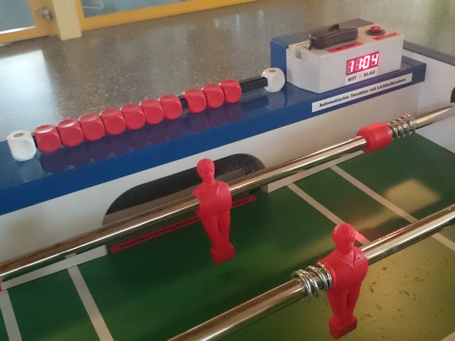
Code for automatic table soccer counter. By teacher Morgenthaler and student Leo at Swiss school www.oszt.ch
*/
// 3 lines importing libraries for the Adafruit display
#include <Wire.h>
#include <Adafruit_GFX.h>
#include "Adafruit_LEDBackpack.h"
// Initailizing the 7-segment display
Adafruit_7segment matrix = Adafruit_7segment();
// Defining varialbes for the two goals
int Rot;
int Blau;
// Defining Arduino's board-LED. For controlling purpose only during coding
#define LEDPIN 13
// Defining the two pins the data connections of the breakbeam sensors
#define SENSORPIN 4
#define SENSORPIN2 2
// Defining the pin for the back to zero button
#define SENSORPIN3 7
// Initalizing and defining states for the breakbeam sensors and the back to zero button
int sensorState = 0, lastState=0;
int sensorState2 = 0, lastState2=0;
int sensorState3 = 0, lastState3=0;
void setup() {
// Initializing Arduino's board LED for output
pinMode(LEDPIN, OUTPUT);
// Initializing pin for input from breakbeam sensor
pinMode(SENSORPIN, INPUT);
// Activating the pullup resistor for this pin to make the two sensor states clear for Arduino
digitalWrite(SENSORPIN, HIGH);
// Same for other breakbeam sensor
pinMode(SENSORPIN2, INPUT);
digitalWrite(SENSORPIN2, HIGH);
// Same for back to zero button
pinMode(SENSORPIN3, INPUT);
digitalWrite(SENSORPIN3, HIGH);
// Start value for goals
Rot = 0;
Blau = 0;
//Define address for display
matrix.begin(0x70);
}
void loop(){
// Next 3 lines: Read and save states of the 2 sensors and the back to zero button
sensorState = digitalRead(SENSORPIN);
sensorState2 = digitalRead(SENSORPIN2);
sensorState3 = digitalRead(SENSORPIN3);
// The following lines are for displaying the the goal values on the display.
// This if argument prevents from displaying a zero with numbers under 10
if(Rot / 10)
// Display position 0 will show the first position of goal variable Rot
matrix.writeDigitNum(0, (Rot / 10) );
// Display position 1 will show the second position of goal variable Rot
matrix.writeDigitNum(1, Rot % 10 );
// A colon will be displayed between the two varialbes
matrix.drawColon(true);
// This if argument prevents from displaying a zero for other variable
if(Blau / 10)
// Display position 3 will show the first position of goal variable Blau
matrix.writeDigitNum(3, (Blau / 10) );
// Display position 4 will show the second position of goal variable Blau
matrix.writeDigitNum(4, Blau % 10 );
// Display everyting above
matrix.writeDisplay();
// 3 if-else arguments following for the two breakbeam sensors and the back to zero button
// If sensor light beam is broken, system reads status low and turns the control LED on
if (sensorState == LOW) {
digitalWrite(LEDPIN, HIGH);
}
// otherwise no power for the control LED
else {
digitalWrite(LEDPIN, LOW);
}
// If SensorState does not differ from lastState...
// (The "!" reverses the signal state to function correclty.
// Without it, the goal values constantly increase when light beams ar UNbroken)
if (sensorState && !lastState) {
// ...The message Unbroken would be displayed on Arduino's serial monitor
Serial.println("1 Unbroken");
}
// If it differs, "Broken" would be displayed and the goal variable Red is increased.
if (!sensorState && lastState) {
Serial.println("1 Broken");
Rot = Rot + 1;
}
// Same for other breakbeam sensor
if (sensorState2 && !lastState2) {
Serial.println("2 Unbroken");
}
if (!sensorState2 && lastState2) {
Serial.println("2 Broken");
Blau = Blau + 1;
}
// Check status of back to zero button
if (sensorState3 && !lastState3) {
}
// If pressed, the serial display would show "reset" and both goal variables are reset to zero.
if (!sensorState3 && lastState3) {
Serial.println("reset");
Blau = 0;
Rot = 0;
// Clears everything displayed on LED
matrix.clear();
}
// Save the last sensor states
lastState = sensorState;
lastState2 = sensorState2;
lastState3 = sensorState3;
}
// End of programm. Restart void loop


_ztBMuBhMHo.jpg?auto=compress%2Cformat&w=48&h=48&fit=fill&bg=ffffff)


Comments