

Hardware components | ||||||
_ztBMuBhMHo.jpg?auto=compress%2Cformat&w=48&h=48&fit=fill&bg=ffffff) |
| × | 1 | |||
 |
| × | 1 | |||
 |
| × | 1 | |||
 |
| × | 1 | |||
| × | 3 | ||||
 |
| × | 1 | |||
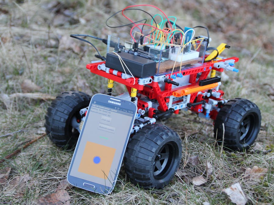
Do you have one of those awesome Lego Power Functions models with electrical motors and servo-motors? In this tutorial I will show you how you can control your Lego model with your Arduino and a minimum of electronic components. I will explain the circuits and programming in detail to make this tutorial easy understandable for beginners. The Lego model you will have to build yourself (if you don't have a son), I won't help you with that.
We will also learn how to use the MIT app inventor to program our own remote control Android app. Soon, you will have your own Lego Mars rover in your backyard!
This is my first Arduino project and my son has a beautiful Lego Technic car model (9398 4X4 Crawler) with Lego Power Functions: one Lego Servo Motor for steering and two Lego L-motors for driving. He allowed me to use the car for this project (as long as I didn't cut up any motor cables). Here, we test the finished prototype:
Understanding the Power Functions wiringFirst, buy some Lego Power Functions Extension wires (item 8886 in the Lego web shop). Next, cut them up (seriously). We will make some "break-out"-cables that have Lego bricks at one end and pins at the other end. Solder the pins on or similar. Here is the wiring explained:
GND stands for Ground which is the negative terminal (-) of the battery pack (anode). C1 and C2 can switch polarity to make the motors and servos switch direction. TechnicRobot has made a nice video explaining everything in detail. (WARNING: you are doing this on your own responsibility. I will not be held responsible if you ruin something!) For the Lego servo connector, you need to solder on pins to all four cables. You can use the light grey plug. For the power cable connecting the battery box with the breadboard, we need only +9 Volt and GND but you have to use the dark grey plug (because you need a male connector):
For the motor cable, we need only to connect C1 and C2 and you can use a light grey plug. (Study the schematics for details).
Controlling a Lego motor with the L293D chipWe want variable speed control for our DC motors and position control for our Lego servo. This is achieved by Pulse Width Modulation (PWM). The Arduino's programming language makes PWM easy to use; simply call analogWrite(pin, dutyCycle), where dutyCycle is a value from 0 to 255. The PWM pins are marked with ~ on your arduino.
The Arduino output pins are 5 Volt and max. 30 mA while the Lego motors need 9 Volt and pull more than 100 mA each. We need some kind of "switching device" in-between. We also want to be able to run the DC motors in both directions. These functions are solved by a so-called H-bridge. We will use the L293D, which contains two H-bridges on one integrated chip, which means we can connect the Lego motors (M) in parallel to one side and the Lego servo (S) to the other side of the chip. (If you want to control the two motors independently you will need a second L293D). The Lego servo also needs to be connected to GND and Lego +9 Volt.
The chip keeps Lego +9 Volt and Arduino +5 Volt completely separated. Never connect them together or you will damage something! But you have to connect all ground lines together and with the L293D ground pins.
From our Arduino, we will use pin 9 to control the motor speed and pins 2 and 5 to control the rotation direction. The Lego servo is controlled like a motor: we connect pin 3 for position and pins 6 and 8 for direction (left or right).
At the top of our program, we define the used Arduino pins as constants. Further, we define some variables that we will use to control the motors:
// Motor control digital output pins defined as global constants
const int controlPin1A = 2;
const int controlPin2A = 5;
const int ENablePin = 9;
// Servo control digital output pins defined as global constants
const int controlPin3A = 6;
const int controlPin4A = 8;
const int servoENablePin = 3;

// Motor control global variables:
int motorSpeed = 0;                          // Motor speed 0..255
int motorDirection = 1;                      // Forward (1) or reverse (0)
// Servo control global variables:
int steering = 0;                            // Servo position 0..255
int steeringDirection = 0;                   // Left (0) and Right (1)
In the setup, we define these pins as outputs with the pinmode() command and then set them to 0 Volt with digitalWrite().
void setup()
{
  //other stuff....

  // Declare digital output pins:
  pinMode(controlPin1A, OUTPUT);      // 1A
  pinMode(controlPin2A, OUTPUT);      // 2A
  pinMode(ENablePin, OUTPUT);         // EN1,2
  pinMode(controlPin3A, OUTPUT);      // 3A
  pinMode(controlPin4A, OUTPUT);      // 4A
  pinMode(servoENablePin, OUTPUT);    // EN3,4

  digitalWrite(ENablePin, LOW);       // motor off
  digitalWrite(servoENablePin, LOW);  // steering centered
}
Now we need to understand how the L293D chip controls the rotation direction of the motors. We have to supply the following signals (High == 5 Volt; Low == 0 Volt):
- EN1,2 1A 2A
- High High Low Motor turns left (Forward; motorDirection == 1)
- High Low High Motor turns right (Reverse; motorDirection == 0)
- EN3,4 3A 4A
- High High Low Servo turns left (steeringDirection == 0)
- High Low High Servo turns right (steeringDirection == 1)
Ok. We are ready to write a subroutine that reads the global variables for direction and speed/position and controls the motors and servo:
void SetMotorControl()
{
 if (motorDirection == 1)               //Forward
   {
      digitalWrite(controlPin1A, HIGH);
      digitalWrite(controlPin2A, LOW);
   }
 else                                   //Reverse
   {
      digitalWrite(controlPin1A, LOW);
      digitalWrite(controlPin2A, HIGH);
   }
 analogWrite(ENablePin, motorSpeed);    //Speed

 if (steeringDirection == 0)            //Left
   {
      digitalWrite(controlPin3A, HIGH);
      digitalWrite(controlPin4A, LOW);
   }
 else                                   //Right
   {
      digitalWrite(controlPin3A, LOW);
      digitalWrite(controlPin4A, HIGH);
   }
 analogWrite(servoENablePin, steering); //Servo position
}
Next, let's build a simple Android app to control the model. (If you want to test the finished app first: I have made it available for you in the Google play store. Here is the link: Arduino RC car bluetooth).
We will use the MIT app inventor 2. MIT App Inventor is an innovative beginner's introduction to programming and app creation. Google's Mark Friedman and MIT Professor Hal Abelson co-led the development of App Inventor. It runs as a web service administered by staff at MIT’s Center for Mobile Learning.
On your Android phone, go to Google Play and install the MIT AI2 Companion app. On your computer, open the link to my RC app in either Firefox- or Chrome-browser (Internet Explorer not supported). You will have to log in using your gmail-address and create an account in order to see the source code. If you open the companion app on your phone, you can look at the source code in the browser, make changes to it and test it immediately on your phone.
In the browser, you will now see the Designer-view of the app:
At the bottom, we see the orange pad with the blue joystickball in it. Now change into the Blocks-view to see the program. The heart of the program is a when-block that keeps track of the movements of your finger touching and dragging the blue joystickball:
The position of your finger is tracked in the two variables currentX and currentY and is used to calculate values for the two variables steering and speed (range: -100..0..+100). First the program checks if your finger is outside the pad and limits the values to +/- 100. If the finger is inside the pad, the program calculates values for steering and speed. Next, the program generates a command-string of the form:
"RC,steering,speed,\n"
The command starts with "RC" for remote control (the idea is that in the future, you might want to have more commands) followed by a comma. Then we send the values for steering and speed. The newline-character ('\n') at the end of the command is a signal to the Arduino that the command is complete. This command-string is sent over bluetooth to the Arduino. For your reference, the string is also displayed on the screen.
Reading bluetooth-commands into the ArduinoIn order to read the Bluetooth command strings, we need to connect a HC-05 Bluetooth module. Have a look at your module:
Mine has 6 pins. We only need four pins. VCC is (positive) supply voltage and GND is ground. The module tolerates 6 Volt supply voltage, which means we can connect it to the arduino 5 Volt power pin. TXD and RXD are the serial signals. We have to cross the lines and connect TXD to arduino RXD (pin 0) and vice versa. Be careful: It states LEVEL: 3.3V which means that the RXD cannot be directly connected to the 5V arduino TXD (pin 1). We have to construct a voltage divider with three 1 kOhm resistors to produce an output voltage which is 2/3 of 5V (see schematics). On the other hand, the TXD signal of 3.3V can be directly connected to Arduino RXD. The Arduino will recognise 3.3 Volt as HIGH.
As pin 0 and 1 are shared with the USB port of your Arduino, you will have to disconnect the RXD and TXD signals from pin 0 and 1 while uploading the program over USB to the board. The upload won't work if you don't disconnect the cables.
Next, you have to pair the HC-05 module with your Android device. Switch Bluetooth on; start the app; press "Bluetooth connect"; make your phone visible and look for a device called HC-05 or similar. Select the device. You will be asked for a code. Press "1234". When you return to the joystick-screen, it should state "connected" in green.
Now, lets look at the code:
// Serial buffer size: calculate based on max input size expected for one command
#define INPUT_SIZE 30


void loop()
{
  // Get next command from serial bluetooth (add 1 byte for final 0)
  char input[INPUT_SIZE + 1];                  // array of type char (C-string)
  //read Serial until new line or buffer full or time out
  byte size = Serial.readBytesUntil('\n', input, INPUT_SIZE);
  // Add the final 0 to end the C-string
  input[size] = 0;

  // Split string which is of the form:  "RC,steering,speed,\n\0"
  char* command = strtok(input, ",");          // command (RC)
  // RCsteering in Range: -100 (left).. 0 .. 100 (right)
  char* RCsteering = strtok(NULL, ",");
  // RCspeed in Range: -100 (full speed reverse).. 0 .. 100 (full speed forward)
  char* RCspeed = strtok(NULL, ",");
  int iRCsteering = atoi(RCsteering);          // convert string into integer
  int iRCspeed = atoi(RCspeed);                // convert string into integer

  //rest of program
}
The string sent by the Android app is read into a special string-construct: a C-string with null-termination. (The 0-character tells the program that it has come to the end of the string). This is done by using the function Serial.readBytesUntil('\n', input, ...), which reads from the serial interface (bluetooth) until it gets a newline-character ('\n'). That way, we keep reading bytes until we have a complete command in input:
"RC,steering,speed,\n\0".
A very efficient way to process input is the string token function, which cuts the string into parts using comma as a delimiter. The first call to strtok() returns "RC". The subsequent parts of the command are then read by passing NULL to strtok(). The returning values are stored in RCsteering and RCspeed. These variables are actually pointers to positions in input. The function atoi() converts them finally into integers. Now, we have:
iRCsteering == -100 (left).. 0 .. +100 (right)
iRCspeed == -100 (reverse).. 0 .. +100 (forward)
We are almost done now. We have to multiply these values by 2.55 before we pass them on to our routine SetMotorControl() (Remember that motorspeed was in the range 0..255). Study the rest of the program in the CODE section, build the circuit and test your remote controlled Lego model!
What's next?Now that you have an Arduino controlling your Lego model, you might want to use that model as a robotics platform: add some ultrasonic ping sensors, program your own obstacle-avoiding logic and make your own self-driving robotic Mars rover. Or add more commands to the remote control and more functions to the model. But first, find a method for the Arduino to figure out that the model has traveled out of range of the bluetooth connection and stop the model. Tell me about your solution.
Soon enough, you will find out that a prototyping breadboard and loose cables are not a good idea for a moving model. Get yourself an adafruit motorshield with big terminal block connectors and rewire and reprogram. This will also free up digital signals that you can use for inputs instead. You might also consider a sensor shield for better connection of your sensors.
Let me know of your exiting projects!


Comments