


Hardware components | ||||||
_ztBMuBhMHo.jpg?auto=compress%2Cformat&w=48&h=48&fit=fill&bg=ffffff) |
| × | 1 | |||
| × | 1 | ||||
 |
| × | 4 | |||
| × | 3 | ||||
| × | 1 | ||||
 |
| × | 1 | |||
 |
| × | 4 | |||
 |
| × | 1 | |||
| × | 1 | ||||
| × | 1 | ||||
| × | 1 | ||||
| × | 1 | ||||
Software apps and online services | ||||||
 |
| |||||
Hand tools and fabrication machines | ||||||
 |
| |||||
| ||||||
This is Tobor, the Arm.
An adventure to the realms of "Are you nuts?" Oh...maybe I think I am. After my other two projects already published here at Project Hub, a kind of a "confidence on simple coding" and my curiosity on making something else to fullfill my nerdiness arised when I start to search and read about robotic arms.
"It look so simple...I can do it... But as my previous projects I would like to built some playable for my young child, without breadboards and fragile "prototype" connections.
I also dreamed about build a fancy Control Panel, where I can manage the Arm and have it autonomous from the PC, safely operated with an external power source, to leave it with a child without worry about a mess with delicate pots, wires, buttons, leds, fragile connections and so far.
So, lets planning...
1 - The Arm will be this "MeArm" style with 4 mini servos (4DOF) we can find so many projects on internet, cheap and funny.
2 - After some reading I did think this project would not requires much knowledge in eletronics... ( I wish...). As a " noob maker" I am really freaked out about have to learn and use transistors, capacitors, CI's and any eletronic stuff other than Arduino board, potenciometers, buttons and leds and resistors...
3 - I really want a sturdy as possible Controlbox to operate the Arm without connections with a PC.
4 - The research showed the main issue with robotic arms is the correct power system. The arduino itself is not capable to deal with 4 servos. I decided to use an external 5V/4A power supply I can connect on an ordinary outlet at home. This is the most expensive item on the budget but I can keep it for other uses.
5 - The Controlbox will need a display (20x4) to show:
5.1 - A Welcome screen;
5.2 -On Manual Mode, the reading of the angles when I turn the pots, mapped from 0 to 180 degrees;
5.3 - On Manual Mode, the display must show what I am writing on memory to program Tobor to work in Automatic Mode. (I will discuss it later).
5.4 - A display screen with a kind of " Program Running >>>"
6 - The Controlbox controls:
6.1 - A red Led to show the power is On;
6.2 - Four potenciometers to control each servo;
6.3 - A switch button between Manul and Automatic Mode;
6.4 - A black button to select the "Memory Positons" to correct saving step mistakes;
6.5 - A green button to save the Servo angles on a array of five variables: memPosition and servos angles (four variables);
6.6 - A red button for a future use.
So...How to put this togheter... I will try to do as many screwed and plugged connections possible to avoid welding. Ok this not a big deal but I really like not to have to weld things.
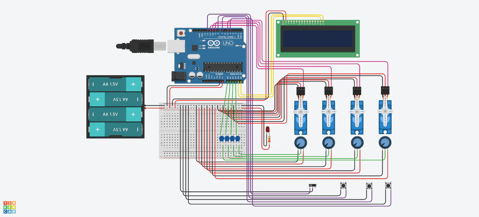
Thinking about the phisical configuration, I build bank of 5V and GND connectors for all wiring needed with an universal board and screwed connectors. The signal pins I use protoboard wires and plugs.
The built up I2C on the 20x4 Display was an eaasy choice: Only four cables to connect.
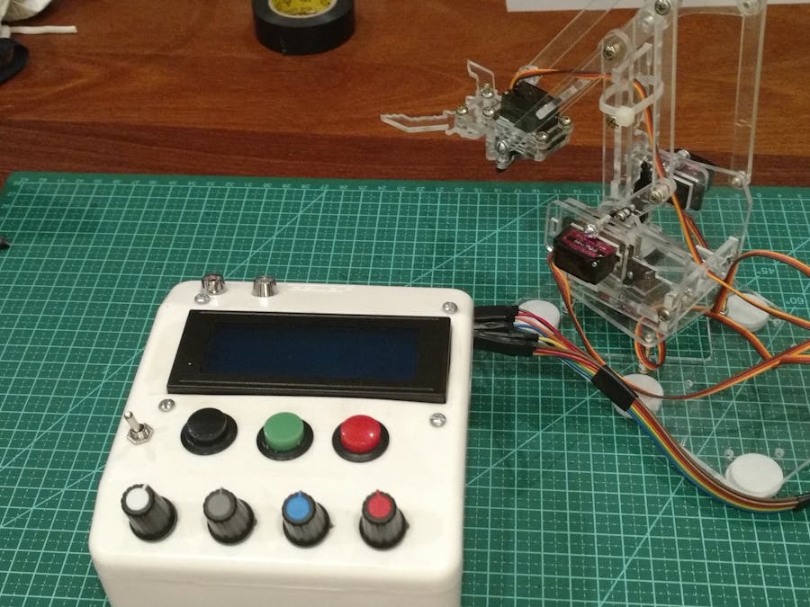
The picture above show all the Controlbox items. The buttons and pots already welded. On the lower left there is the 5V/GND banks. The arduino is mounted with spacers and 3M double sided tape. On the left side of the Controlbox there are one hole for the USB cable and another for the P4 external power in (not the arduino one!)
The holes were made with apropriate drilling tools I already have. The display hole was the big challenge. It was made with a blade, very, very slowly and took a lot of time and effort. I think at the end it was acceptable. The display is little offset due to the I2C module connections.
An eletrical tape piece secure signal wires in place. Same thing were doing for the analog and power wiring on the other Arduino edge.
Voilá!
Tired?
Now lets talk about the code logics.
Obviously, there is MUCH TO IMPROVE. I think to reach the "point B from the point A", one experienced programmer goes straight when I do this in a "ZigZag" mode. Sorry I do not have enough english and for the same reason I write this the way my written language knowledge permits...
Several examples for servo.write(), analogoRead(), pinMode(), mapping pots we can easily find on internet and I would like to focus on the mais issue, that was the "logic" I adopted.
When thinking about Manual Operation, there was no challenge at all. analogRead(), map() and display configuration to show values.
A Switch button to toggle between Manual and Auto modes. On Auto Mode, the code reads the stored positions of the servos one at a time.
The green button:When it is pressed, the "memory position" increase by one and the angles of all four servos were stored in a Array of 5 variables.
I need to position the Arm in such a way to open the claw, reach an object, grab it, rise/move to another point, open the claw to release and loop this forever. For each group of movements I press green button to store the positions.
If I make a mistake when pressing de the green button, I cycle the "memory position" to the correct step, pressing the black button.
The code permits only Ten memory positions of four servos angles. This "Ten positions" is a number I figured out to a whole cycle of Arm movements before automatic mode loop. This can be increased by simple coding, addind more memory positions arrays and move servos functions.
Automatic Mode
When the Switch button is toggled to Auto Mode, a bunch of code functions will move the servos accordingly to the total memory positions stored and loop it. Here is when "the magic happens!" the code is so simple I am amazed.
On the Display, a message "Program Running" with an "animated" " > " characther make things "professional...".
If there is no memory positions previously stored, a message " Empty Memory" is displayed.
Issues and future challengesDeal with those fragile mini servos can be tricky. I fried two. I do not know exactly why, but sometimes they get very hot. I guess this can be a current problem. Calibrate them prior to mount the Arm is important.
The movement of the servos is also a thing to improve. I am reading about install 100nF capacitors on signal wires of the potenciometers.
I am also about to try the " VarSpeedServo.h" library to make servos moving smothly.
I did not deal with "debouncing" issues. I have been reading about it.
Arduino EEPROMFor now, if the power is down, the memory stored is lost. I am reading about using the Arduino's EEPROM to keep the memory stored. This will be very interesting but I need to study and learn more to do this.
MeArm:This "MeArm" arm is fine and cheap. It is funny to build and set up. Instructions are widely available on internet. The acrylic material seems to be more resistant then mdf I suppose.
No suprise if in future I get a bigger aluminium Arm with bigger servos...The temptation is to build a 5DOF or even more degrees of freedom witch means I will need a bigger Controlbox...
About the NameThis arm is named after "Tobor the Great", a 1954 sci-fi movie, with this description at Wikipedia:
"In a review in The New York Times, Tobor the Great is characterized as "This children's sci-fi adventure (that) chronicles the friendship between an 11-year-old and his grandfather's robot Tobor, who was designed to explore deep space."
My "Tobor" is not as smart or dramatic, but my son really love it.
I hope you enjoy and make comments! Tobor will thank you all!


Comments