


Hardware components | ||||||
| × | 1 | ||||
| × | 1 | ||||
| × | 3 | ||||
| × | 1 | ||||
| × | 1 | ||||
| × | 1 | ||||
| × | 1 | ||||
| × | 1 | ||||
| × | 1 | ||||
Software apps and online services | ||||||
| ||||||
| ||||||
Hand tools and fabrication machines | ||||||
| ||||||
| ||||||
 |
| |||||
In villages and towns where electricity cut-offs are a daily challenge, one of the first things to go down is the Wi-Fi router. This means no internet for online classes, no work calls, no streaming, and no communication with the outside world. For students like me, it was more than an inconvenience—it was a barrier.
That’s why I designed a Mini UPS as a tool for routers. It’s not just another electronic build—it’s a problem-solving tool, compact and efficient, that ensures your router keeps running during power failures. While big inverters power everything in a home, this tool is built with one focused purpose:keeping the internet alive.
Using Autodesk Fusion 360, I created a professional-grade enclosure that neatly fits all the electronics while keeping the build compact and durable. The design is practical, easy to assemble, and affordable—making it accessible to students, makers, and anyone who depends on uninterrupted connectivity.
It solves a real-world problem with simplicity and reliability. It proves that sometimes the best tools are not the biggest or most complex—they’re the ones that quietly save the day when you need them most.
SuppliesTo start this project, I designed this diy mini WiFi UPS CAD using Fusion 360. It’s a simple and compact design that’s easy to print and assemble. If you’d like to view or edit the model, you can open it directly in your browser using the Fusion 360 web viewer. Feel free to customize it however you like.
For 3D Printing, You can directly download the required STL files below:
- Body.stl
- Cover.stl
For 3D printing, I Recommend PCBWay, a professional 3D printing service known for its high precision, affordable pricing, and wide range of material choices. They support advanced technologies like SLA, SLS, MJF, and FDM, delivering smooth and durable parts that are ideal for both prototypes and final builds.
One of the best things about PCBWay 3D printing is their fast turnaround time and reliable worldwide shipping, making it super convenient for hobbyists, students, and professionals alike. Whether you’re just getting started or working on a serious engineering project, PCBWay is a great choice.
👉 Use the link to get an exclusive discount on your first 3D printing order from PCBWay
Step 2: DC Jack AssemblyInsert the DC 5525 female jack into its dedicated slot on the cover and secure it with a small amount of super glue, making sure the orientation is correct.
Step 3: Capacity Indicator AssemblyPlace the battery capacity indicator module into its slot on the cover and fix it with a small amount of super glue, ensuring it sits flush and aligned.
Step 4: XT60 Connector AssemblyInsert the XT60 connector into its slot on the cover and secure it firmly with a small amount of super glue, keeping the orientation correct for easy connection later.
Step 5: Switch AssemblyPlace the switch into its slot on the cover and fix it securely with a small amount of super glue, making sure it is properly aligned for smooth operation.
Step 6: Charging BatteryBefore assembling the 3S pack, it’s important to fully charge each 18650 cell. This ensures all the batteries start at the same voltage, which is critical for safety and long-term performance. I used my XTAR VX4 smart charger to charge the cells individually before wiring them into the pack.
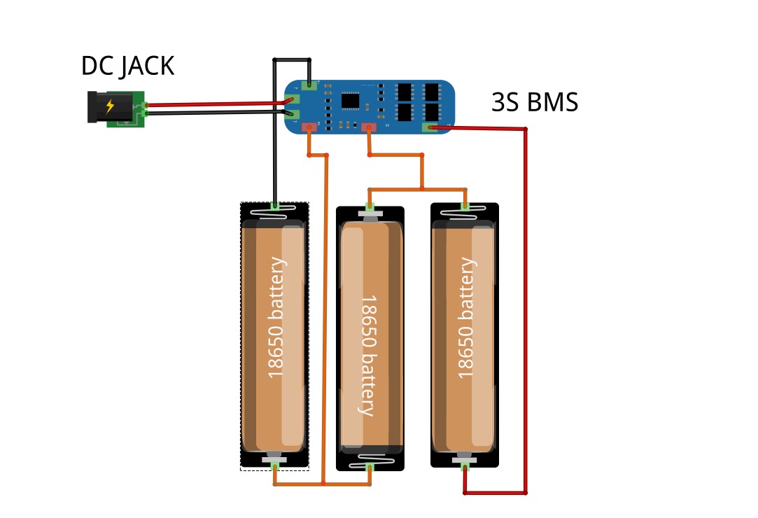
Step 7: 3S Battery PackConnect the three 18650 cells in series to form a 3S battery pack (11.1V nominal). Follow the wiring exactly as shown in the diagram:
- Cell 1 (-) → B– of BMS
- Cell 1 (+) → Cell 2 (–)
- Cell 2 (+) → Cell 3 (–)
- Cell 3 (+) → B+ of BMS
- Junction between Cell 1 (+) & Cell 2 (–) → B1 of BMS
- Junction between Cell 2 (+) & Cell 3 (–) → B2 of BMS
Use the P+ (red wire) as the positive input/output and the P– (black wire) as the negative input/output.
⚠️ Safety Note: Always verify polarity twice before soldering, and keep connections insulated to avoid shorts or overheating.
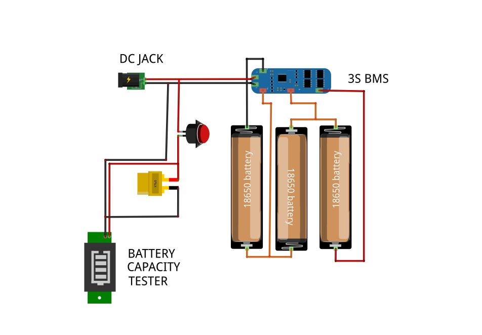
Step 8: ConnectionOnce the battery pack is complete, Now it’s time to wire everything together carefully. Follow the sequence to avoid mistakes, you can also check the provide circuit Diagram for clear understanding.
- DC Jack positive (+) → Switch → XT60 connector + Battery Capacity Indicator
- DC Jack negative (–) → Direct to BMS negative (P–)
- BMS output (P+ / P–) → Goes to XT60 connector and Battery Capacity Indicator
This ensures proper charging through the DC jack, balanced protection via the BMS, and safe output through the XT60.
Step 9: Battery Assembly in CaseInsert the 3S battery pack into the 3D-printed case carefully, making sure it fits in the correct orientation. Once positioned, apply hot glue around the edges to secure the pack firmly in place and prevent movement inside the case.
Step 10: Final AssemblyPlace the cover onto the case and secure it with super glue. Before sealing, carefully double-check all wiring connections to ensure everything is correct and secure. Once confirmed, close the case firmly for a clean and durable finish.
Step 11: Prepare ConnecterTo make the UPS more versatile, I prepared two connectors: one DC-to-DC connector for direct input/output use, and another XT60-to-DC connector for connecting the battery pack or powering external devices. I used 26 AWG wire, which is flexible and suitable for the current requirements.
- DC-to-DC connector → Direct input/output
- XT60-to-DC connector → Battery pack or external device
These connectors make it easy to switch between charging and power delivery, adding more flexibility to the UPS.
Step 12: TestingAfter assembly, make sure to fully charge the Mini UPS with a 12V adapter for optimal performance. Once charged, Connect it to your WiFi router to ensure it runs smoothly during power cuts. The system can also be used as a 12V power supply, or as a 12V battery pack for powering external devices.
- UPS Mode → Powers router during outage
- Power Supply Mode → Works like a 12V adapter
- Battery Pack Mode → Acts as a portable 12V source
This makes the mini UPS not only a backup solution but also a multi-purpose power tool for different applications.
ConclusionThe Mini UPS for WiFi routers is not just another backup device—it is a versatile power tool designed to keep you connected without interruption. Its compact size, multi-functionality, and highly polished Fusion 360 design make it superior to bulky and costly commercial alternatives. By blending reliability with elegance, it delivers both performance and practicality in a single, refined package.
This project proves how innovation and craftsmanship can turn a simple idea into an indispensable everyday tool—one that not only meets expectations but has the potential to outperform and redefine traditional solutions.
Happy Making 🤞🏻


_t9PF3orMPd.png?auto=compress%2Cformat&w=40&h=40&fit=fillmax&bg=fff&dpr=2)


Comments