


In this comprehensive tutorial, you will learn how to interface the DFRobot M0601 Motor (Direct-Drive Hub Motor for AGV) using the RS485 communication protocol. We will guide you step-by-step through testing the motor with raw Hex commands, automating movements with Python scripts, and finally controlling it via MotorLink—an intuitive, browser-based digital twin application.
MotorLink Web App
MotorLink is a free, open browser-based control application designed to simplify interfacing with the M0601 Motor. It handles all RS485 protocol complexity automatically using the Web Serial API, requiring no software installation or backend.
Key Features:
- Digital Twin Visualization: Real-time on-screen sync of the motor's movement.
- Full Motor Control: Intuitive sliders and presets for Velocity, Current, and Position loop modes.
- Live Telemetry & Graphs: Monitor speed, current, position, and temperature in real time.
- Advanced Tools: Integrated ID manager, raw hex editor, and communication packet log.
MotorLink App Git Repo:https://github.com/MukeshSankhla/MotorLink.git
Supplies- 1x M0601
- 1x Rainbowlink
The M0601 is a high-performance direct-drive hub motor from DFRobot's FIT1042 series. Based on an integrated FOC (Field-Oriented Control) servo architecture, it combines an outer-rotor brushless motor, encoder, and servo driver into a single compact unit — eliminating the need for external reducers and delivering smooth, low-noise torque directly to the wheel.
Unlike conventional geared motors, the M0601 uses direct-drive technology, meaning the wheel is the rotor. This gives it:
- Zero backlash and near-zero mechanical losses
- Ultra-low noise (suitable for indoor environments)
- Smooth torque at low RPM without cogging
- Precise closed-loop control at up to 500Hz command rate
Communication is entirely over RS485 using a compact 10-byte frame protocol, making it simple to integrate with any microcontroller, single-board computer, or PC via a USB-to-RS485 adapter.
2. Versions — Left & Right OrientationThe M0601 is available in two mirror-image variants to suit different chassis and robot designs:
Note: The rubber tires have a directional tread pattern. If you need to change the tire angle, remove the 3× M2.5×8 hex screws on the front black cover, detach the cover, remove the tire, rotate it to the correct orientation, and reinstall.
The two versions are mechanically and electrically identical — only the tire mounting direction differs. Either motor can be commanded to spin in either direction via the sign of the velocity/current value.
3. SpecificationsThe M0601's combination of direct drive, RS485 multi-drop, and three control modes makes it ideal for:
- Mobile Robots — AGV drive wheels, differential-drive and holonomic platforms
- Balance Robots — Precise velocity control for self-balancing systems
- Robot Joints — Torque-controlled arms and legs using current loop mode
- Service Robots — Indoor delivery, hospitality, security patrol robots
- Fitness Equipment — Smart resistance wheels with torque feedback
- Camera Sliders / Gimbals — Position loop for repeatable angular control
- Industrial Automation — Conveyor drive wheels on a shared RS485 bus
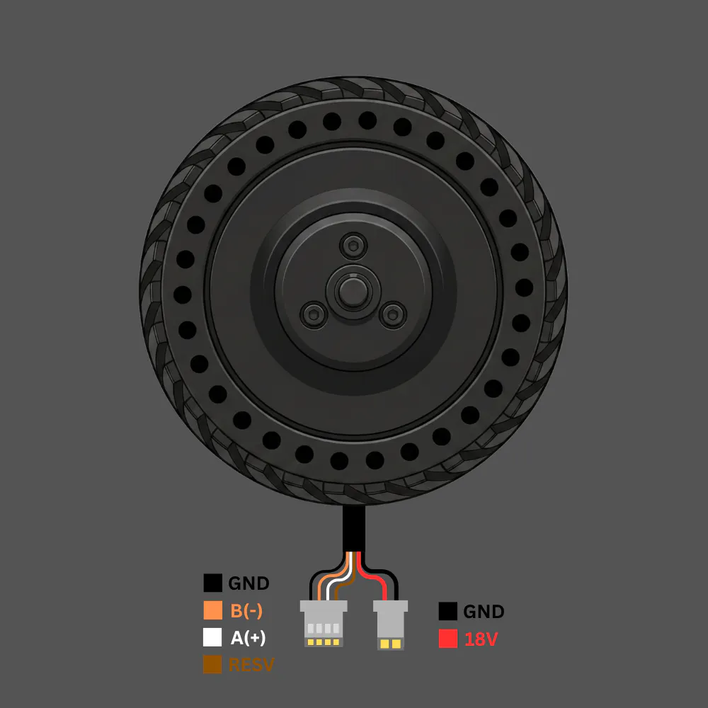
The motor has two cable connectors:
Signal Cable (4-pin JST connector)
Power Cable (2-pin connector)
RS485 is a differential 2-wire bus. Multiple motors can share the same A/B pair, each with a unique address (ID 0x01–0xFE).
Connection Diagram
PC / Microcontroller
        │
   USB-to-RS485 Adapter
        │
   ┌────┴────┐
   A(+)   B(-)   GND
    │       │      │
   White  Orange  Black ──► Motor Signal Connector (4-pin)
                         ──► Brown wire also to GND

   18V DC power supply ──► Red/Black Power Connector (2-pin)
Key Rules
- A/B polarity matters. If the motor doesn't respond, swap Orange and White.
- Brown wire must connect to GND — it is the RS485 signal ground reference. Leaving it floating causes communication errors, especially on longer cables.
- 18V power is separate from the RS485 logic. The motor will not spin without power even if RS485 communication is working.
- Only one motor on the bus when setting or querying IDs — address conflicts cause garbled responses.
- For cable runs longer than 1 metre, add a 120Ω termination resistor across A and B at the far end of the bus.
Here's the content converted for Hackster.io (which uses Markdown but doesn't render HTML tables):
7. Interfacing with RainbowLink (TEL0185)The DFRobot RainbowLink (TEL0185) is a 4-channel USB-to-multi-protocol converter supporting RS485, RS232, and TTL on a single USB connection. It is the recommended PC interface for the M0601.
Step-by-step Setup
Step 1: Install Driver
The RainbowLink uses a CH343 chipset. Install the driver from the DFRobot wiki or directly from WCH: CH343 Driver Download
Step 2: Connect Wires
- Orange (B−) → A terminal on RS485 channel
- White (A+) → B terminal on RS485 channel
- Black (GND) → GND terminal
- Brown (RESV) → GND terminal (recommended)
⚠️ If the motor doesn't respond, swap Orange ↔ White — the A/B labelling on the motor is inverted relative to some converters.
Step 3: Identify the COM Port
After plugging in the RainbowLink via USB:
- Windows: Open Device Manager → Ports (COM & LPT) → note the COM number (e.g. COM13)
- Linux/Mac: Run
ls /dev/tty*and look for/dev/ttyUSB0or similar
Step 4: Serial Settings
Baud Rate:    115200
Data Bits:    8
Parity:       None
Stop Bits:    1
Flow Control: None / OFF
Step 5: Quick Test with Hercules
Open Hercules SETUP utility → Serial tab → configure settings above → Open. In the Send box, tick HEX, type the ID query frame below, and click Send:
C8 64 00 00 00 00 00 00 00 DEA response in the Received window confirms the motor is wired and powered correctly.
8. Communication ProtocolAll motor communication uses 10-byte frames at 115200 baud, 8N1, half-duplex RS485.
Send Frame Structure (Drive Command)
Byte     Field           Description
------   -------------   ------------------------------------------------
DATA[0]  Motor ID        Target motor address (0x01–0xFE)
DATA[1]  Command type    0x64=drive, 0x74=feedback query, 0xA0=mode switch
DATA[2]  Value HIGH      High byte of INT16 payload
DATA[3]  Value LOW       Low byte of INT16 payload
DATA[4]  Reserved        Always 0x00
DATA[5]  Reserved        Always 0x00
DATA[6]  Acceleration    Valid in velocity mode; 0 = default (1 = 0.1ms/rpm)
DATA[7]  Brake           0xFF = electric brake (velocity mode only); else 0x00
DATA[8]  Reserved        Always 0x00
DATA[9]  CRC8            CRC-8/MAXIM of bytes DATA[0]–DATA[8]
CRC-8/MAXIM Algorithm
Polynomial: x⁸ + x⁵ + x⁴ + 1 (reflected: 0x8C)
def crc8_maxim(data):
    crc = 0
    for byte in data:
        crc ^= byte
        for _ in range(8):
            crc = (crc >> 1) ^ 0x8C if (crc & 0x01) else (crc >> 1)
    return crc
You can also verify frames at crccalc.com — select CRC-8/MAXIM.
Control Modes:
Mode           Mode Byte   Value Range          Unit
-----------    ---------   ------------------   ---------------
Current Loop   0x01        −32767 to +32767     ≈ −8A to +8A
Velocity Loop  0x02        −330 to +330         RPM
Position Loop  0x03        0 to 32767           0° to 360°
⚠️ Motor speed must be below 10 RPM before switching to Position Loop mode.
Polling Requirement
The motor uses a polling protocol. A single command does not sustain motion — the host must repeatedly send the drive command at ≥20ms intervals (50Hz recommended). Sending 0 RPM or the brake frame will halt the motor.
9. Verified Command ReferenceAll frames below are CRC-8/MAXIM verified.
Mode Switch:
Switch to Velocity Loop
01 A0 00 00 00 00 00 00 00 02Send 3–5 times. No feedback returned.
Switch to Current Loop
01 A0 00 00 00 00 00 00 00 01Send 3–5 times. No feedback returned.
Switch to Position Loop
01 A0 00 00 00 00 00 00 00 03Speed must be <10 RPM first.
Utility Commands:
Feedback Query
01 74 00 00 00 00 00 00 00 04Returns 10-byte status frame.
Brake (Velocity Mode)
01 64 00 00 00 00 00 FF 00 D1Electric brake.
ID Query (Broadcast)
C8 64 00 00 00 00 00 00 00 DESingle motor on bus only.
Set Motor ID to 0x01
AA 55 53 01 00 00 00 00 00 CBSend exactly 5 times. One motor on bus.
Velocity Loop (−330 to +330 RPM)
Speed      Frame
--------   ------------------------------
−100 RPM   01 64 FF 9C 00 00 00 00 00 9A
 −50 RPM   01 64 FF CE 00 00 00 00 00 DA
   0 RPM   01 64 00 00 00 00 00 00 00 50
 +50 RPM   01 64 00 32 00 00 00 00 00 D3
+100 RPM   01 64 00 64 00 00 00 00 00 4F
Current Loop (−32767 to +32767)
Value    Approx. Current   Frame
-------  ---------------   ------------------------------
−10000   ~−2.44A           01 64 D8 F0 00 00 00 00 00 78
 −5000   ~−1.22A           01 64 EC 78 00 00 00 00 00 D3
 −2000   ~−0.49A           01 64 F8 30 00 00 00 00 00 08
      0   0A               01 64 00 00 00 00 00 00 00 50
 +2000   ~+0.49A           01 64 07 D0 00 00 00 00 00 27
 +5000   ~+1.22A           01 64 13 88 00 00 00 00 00 A7
+10000   ~+2.44A           01 64 27 10 00 00 00 00 00 57
Position Loop (0–32767 = 0°–360°)
Raw Value   Angle    Frame
---------   ------   ------------------------------
        0   0°       01 64 00 00 00 00 00 00 00 50
    10000   ~109.8°  01 64 27 10 00 00 00 00 00 57
    20000   ~219.7°  01 64 4E 20 00 00 00 00 00 5E
30000 ~329.5° 01 64 75 30 00 00 00 00 00 A7The motor responds to drive commands and feedback queries with a 10-byte frame.
Protocol 1: Drive Command Response
Byte       Field            Decode
--------   --------------   ------------------------------------------
DATA[0]    Motor ID         Responding motor's address
DATA[1]    Mode             0x01=Current, 0x02=Velocity, 0x03=Position
DATA[2–3]  Torque Current   int16 = (D[2]<<8) | D[3]
DATA[4–5]  Velocity         int16 = (D[4]<<8) | D[5]
DATA[6–7]  Position         int16 = (D[6]<<8) | D[7]
DATA[8]    Error Code       Bitmask (see below)
DATA[9]    CRC8             CRC-8/MAXIM of DATA[0]–DATA[8]
Protocol 2: Feedback Query Response
Byte     Field                Decode
-------  -------------------  -------------------------------------------
DATA[6]  Winding Temperature  °C (uint8, direct)
DATA[7]  U8 Position          0–255 → 0°–360° (degrees = value × 360 / 255)
Error Code Bitmask
Bit     Meaning
------  --------------------------
BIT0    Sensor error
BIT1    Overcurrent error
BIT2    Phase overcurrent error
BIT3    Stall / locked rotor error
BIT4    Troubleshooting flag
BIT5–7 ReservedExample:0x22 = 0b00100010 → Phase overcurrent + Overcurrent active simultaneously.
Protection        Threshold   Reset
---------------   ---------   -------------------------------
Bus Overcurrent   3A          Auto after 5 seconds
Over-temperature  80°C        Auto when winding temp drops below 75°C
Phase Overcurrent 4.6A        Auto after 5 seconds
Stall (Locked)    Blocked >5s Auto after 5 seconds
During a protection event the motor stops responding to drive commands. The error code byte in the feedback frame indicates which protection is active.
12. Python Code ExamplesRequirement: Install pyserial before running any of these scripts.
pip install pyserialEdit the COM_PORT variable at the top of each script to match your system.
Requirement: Install pyserial before running any of these scripts.pip install pyserialEdit theCOM_PORTvariable at the top of each script to match your system.
12.1 Motor Scan
This script performs a two-stage scan to discover all M0601 motors on the RS485 bus.
How it works:
- Stage 1 — Broadcast query: Sends the special ID query frame
C8 64 00 ... DEwhich all motors respond to simultaneously. This gives an instant result if only one motor is connected. - Stage 2 — Full poll: Iterates through every possible address from
0x01to0xFE, sending a feedback query to each and listening for a reply. This catches motors whose IDs were previously changed from the default.
The script prints a clean summary at the end listing all detected IDs, and tells you exactly what value to set MOTOR_ID to in the other scripts.
Code Link:https://github.com/MukeshSankhla/MotorLink/blob/master/examples/m0601_scan.py
12.2 Motor Operations
This script demonstrates all three control modes interactively from the keyboard — the most complete starting point for testing motor behaviour.
How it works:
- On startup it opens the serial port and sends the ID query to confirm the motor is online.
- It switches to Velocity Loop mode by default (the motor's factory default).
- A polling loop runs in the background at 50Hz, continuously sending the current command frame. This is required because the M0601 uses a polling protocol — it will not sustain motion from a single command.
- Keyboard input changes the active command, mode, or stops the motor. The polling loop picks up the new command on the very next iteration without interruption.
Code Link:https://github.com/MukeshSankhla/MotorLink/blob/master/examples/m0601_operations.py
12.3 Motor ID Change
This script safely changes a motor's ID address on the RS485 bus.
How it works:
- It first queries the bus to confirm exactly one motor is present and reads its current ID.
- It then sends the ID set frame (
AA 55 53 [NEW_ID] 00 00 00 00 00 00) exactly 5 consecutive times — the motor requires 5 consecutive identical frames to commit the new ID to non-volatile memory. - After setting, it immediately sends an ID query to verify the new ID is active.
⚠️ Only one motor must be connected to the bus during this operation. If multiple motors are present, they will all receive the same new ID and conflict on the bus.
Code Link:https://github.com/MukeshSankhla/MotorLink/blob/master/examples/m0601_set_id.py
12.4 Motor Parameter Monitoring
This script continuously polls the motor's feedback frame and prints a live terminal dashboard showing all real-time parameters: speed, current, position, winding temperature, and fault status.
How it works:
- Sends the Protocol-2 feedback query frame (
01 74 00 ... 04) at a configurable interval (default 200ms). - Parses each 10-byte response to extract: mode, torque current (INT16 → Amps), velocity (INT16 → RPM), winding temperature (°C), angular position (U8 → degrees), and the error code bitmask.
- Decodes the error bitmask into named fault descriptions.
- Prints an updating single-line dashboard that overwrites itself in the terminal.
- Logs all readings to a CSV file for later analysis.
Code Link:https://github.com/MukeshSankhla/MotorLink/blob/master/examples/m0601_monitor.py
Sample terminal output:
[13:15:36.962] # 288 Mode: Velocity | Speed: +100 RPM | Current: +0.070 A | Pos: 71.6° | Temp: 33°C | 🟢 OKSample CSV output:
timestamp,motor_id,mode,speed_rpm,current_a,temp_c,position_deg,error_code,error_str,raw_hex
13:15:36.962,1,Velocity,100,0.07,33,71.6,0x00,OK,01 02 00 0A 00 64 21 59 00 F5Working with raw RS485 hex frames manually is error-prone and slow. To solve this, MotorLink was built as a free, open browser-based application that handles all the protocol complexity automatically.
🔗 Live App: https://mukeshsankhla.github.io/MotorLink/
Compatible Motors
How It Works
MotorLink runs entirely in the browser using the Web Serial API — no installation, no backend, no drivers beyond the USB-RS485 adapter driver.
Browser (MotorLink) ──► Web Serial API ──► COM Port ──► RainbowLink TEL0185 ──► RS485 ──► M0601 MotorGetting Started
- Connect the M0601 to your RainbowLink as described in Section 7
- Power the motor from an 18V DC supply
- Open https://mukeshsankhla.github.io/MotorLink/in Chrome or Edge
- Click Connect, select your COM port from the browser dialog, click Open
- MotorLink automatically sends an ID query and reads the motor's current parameters — the UI adjusts itself to match the motor's active mode
⚠️ Web Serial API is supported in Chrome 89+ and Edge 89+ only. Firefox and Safari are not supported.
Features
🔌 Auto-initialization
On connect, MotorLink automatically sends the broadcast ID query and reads the motor's current operating mode. The UI sets itself to match — no manual configuration needed.
🌀 Digital Twin Motor Visualization
The centre panel displays a real-time digital twin of the physical motor — a rendered hub wheel that rotates in sync with the actual motor. The rotation speed, direction (CW/CCW), and status (STATIONARY / SPINNING / BRAKING) all reflect the live feedback from the motor. When the motor spins at 100 RPM counter-clockwise, the on-screen wheel spins at the same rate and direction, giving you an immediate visual confirmation of what the physical motor is doing without looking away from the interface.
⚡ Velocity Loop Control
- RPM slider: −330 to +330
- Quick action buttons: −100, −50, STOP, START, BRAKE, +50, +100
- Configurable acceleration parameter
- Polls at 50Hz while active
- Electric brake with a single click
🔋 Current Loop Control
- Current slider: −32767 to +32767 (displayed as Amps)
- Preset buttons for common torque values
- Ideal for torque-controlled applications like robot joints and exoskeletons
🎯 Position Loop Control
- Target position input with raw value and live degree display
- Commands the motor to rotate to an exact angular position
- Motor speed must be below 10 RPM before switching to this mode
🪪 ID Manager
- Scan — broadcasts ID query and reports detected motor with its current ID
- Full scan — polls all addresses 0x01–0xFE to find all motors on the bus
- Set ID — change motor address; sends the command 5× automatically and shows a single-motor warning before proceeding
📡 Raw Hex Editor
- Type any 9-byte command frame in hex
- CRC-8/MAXIM automatically computed and appended, showing the full 10-byte frame
- Send once or in a configurable repeating loop
📊 Live Telemetry Metrics
- Speed — real-time RPM value + mini line chart
- Current — real-time Amps value + mini line chart
- Position — raw value + degrees + circular dial gauge that mirrors the motor's actual angle
- Temperature — winding temperature in °C with a gauge arc
- Error Code — displayed as hex with decoded fault names (Overcurrent, Stall, Phase Overcurrent, Sensor Error)
📈 Real-time Performance Graph
Combined speed and current telemetry plotted on a shared time axis, updating at 200ms intervals. The graph retains the last 60 seconds of data, making it easy to observe acceleration ramps, load changes, and thermal step responses.
📋 Communication Packet Log
- Every sent and received frame logged with millisecond-precision timestamps
- Colour-coded entries: TX (blue) / RX (green) / System (grey) / Error (red)
- Collapse status poll checkbox — suppresses high-frequency polling entries so you can read meaningful events without scrolling through thousands of identical lines
- Auto-scroll checkbox — keeps the log pinned to the latest entry
- Export button — download the full log as a CSV file for offline analysis
⚠️ Read before operating the motor.
- The motor will start rotating after certain commands are sent. Do not touch any rotating parts.
- If the motor is not secured to a frame or chassis, always be ready to cut power immediately.
- Start with low speeds (50–100 RPM) when testing for the first time.
- The motor generates significant torque. Ensure it is firmly mounted before commanding movement.
- In case of unexpected behaviour, use the red STOP button in MotorLink, or disconnect the 18V power supply.
- Never exceed 18V on the power supply.
- Allow the motor to cool if the winding temperature exceeds 70°C — protection triggers at 80°C.
- The motor must be stationary (< 10 RPM) before switching to Position Loop mode.


Comments