I recently contracted to have a whole house humidifier installed. It requires an outdoor thermistor. Unfortunately, the installers could not run the wire to properly install a new one. Since there was one already installed at my AC unit for my fresh air intake damper, I began to look for a device to take that one input and supply two outputs to feed both the humidifier and air intake controllers. I didn't find one for that style of thermistor but found some in Italy that were for a different style thermistor and range for about $100.
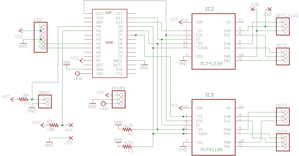
I had previously worked with digipots for an interface to my hvac system controller so I started looking for one that would suffice over the useable range. The MCP42100 is a 100K digipot that is SPI. It has 256 steps so there is about 400 ohm resolution.
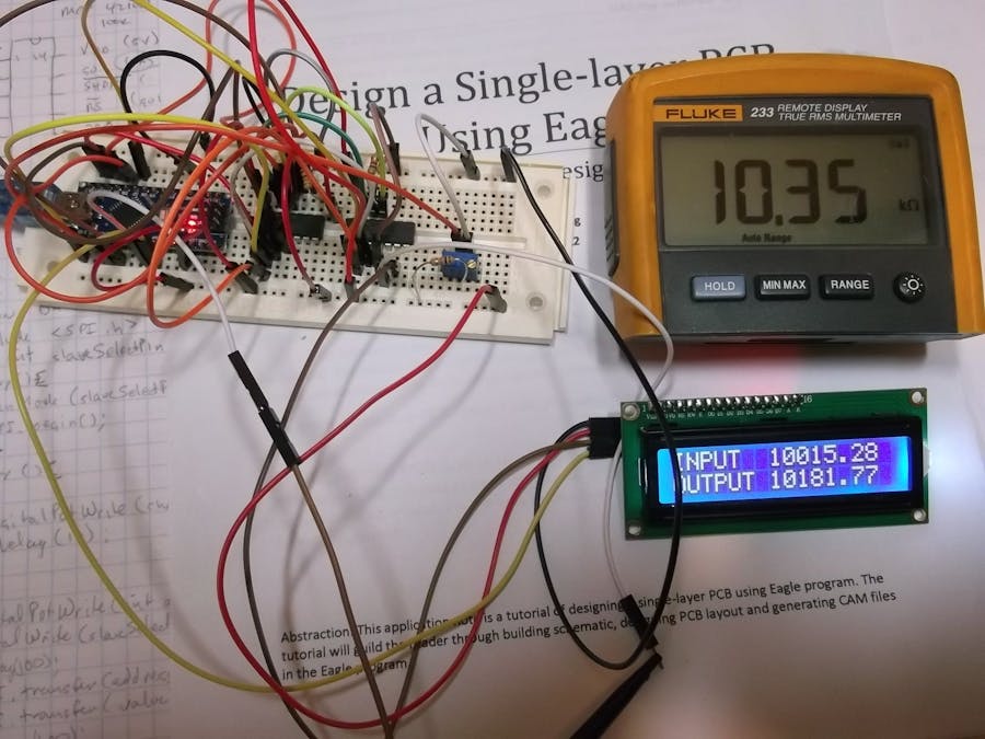
I had some 16x2 LCD's and I2C backpacks squirreled away so I used them to provide input and output resistance readout. To supply the output resistance readout value, I incorporated some jumpers (J1A-J1B and J2A-J2B) that would allow using one of the digipots to drive an analog input to the NANO.
Bear in mind, that with some software changes, you can connect the digipots in series or use different range digipots to change the range and resolution. For my project, I only needed to cover about 100K of resistance while the thermistor is capable of over 200K.
The wipers for these digipots are low current, so you must be careful as to how much load there is on them. That being said, I have driven LEDS with them although you might not think so by the specs. I incorporate SPI and I2C in this project without issue.
To be truthful, I did not end up using this circuit as I properly installed another thermister for the controllers in about two hours. However, I thought someone may find interest in this circuit.


Comments