

Hardware components | ||||||
 |
| × | 1 | |||
_zhWsCcSEcl.jpg?auto=compress%2Cformat&w=48&h=48&fit=fill&bg=ffffff) |
| × | 1 | |||
 |
| × | 1 | |||
| × | 1 | ||||
Hand tools and fabrication machines | ||||||
 |
| |||||
1 / 29 • Also, I was 18yrs old when this Hackster was created
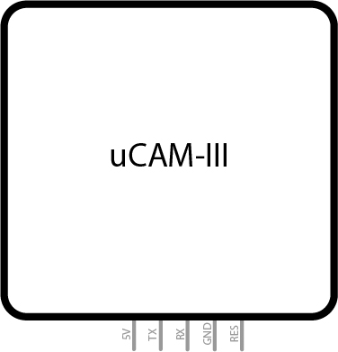
uCAM-III 1Fritzing part Image
First time doing any art like this, I was very proud of the results! I normally use Adobe illustrator to make stuff with a laser cutter.


ParticleArgon_DynamicColorRange
C/C++I originally planned on using the particle argon alone but this code was simplified greatly due to camera issues.
Description: Sends a signal to an ESP32 and flashes a colored LED which outputs two different pictures.
Description: Sends a signal to an ESP32 and flashes a colored LED which outputs two different pictures.
/*
 * Project DynamicColorRange_Program
 * Description: Sends a signal to an ESP32 and flashes a colored LED which    outputs two different pictures.
 * Author: Caden Gamache
 * Date: 04/02/2023 - 04/19/2023
 */
SYSTEM_MODE(SEMI_AUTOMATIC);

/***************************** Declare Variables *****************************/
// General for loop variables
int i, j;

// Pins
const int REDPIN = A5, GREENPIN = A4, BLUEPIN = A3, BUTTONPIN = A2, CAMERAPIN = A0, ARGONLEDPIN = D7;

// Color declaration and array storage
const int BLACK = 0, RED = 1, ORANGE = 2, YELLOW = 3, GREEN = 4, CYAN = 5, BLUE = 6, PURPLE = 7, WHITE = 8;
const int COLOR[] {BLACK, RED, ORANGE, YELLOW, GREEN, CYAN, BLUE, PURPLE, WHITE};
int currentColor = 1;

// Brightness (Percent)
float BRIGHTNESS = 100.0;

// Button setup
bool buttonPressed, snapPicture, repeatBlock;

/****************************** Create Prototypes *****************************/
// Takes in a chosen color (8 total) and brightness and sends the proper voltage to the three pins of a 3W LED to get the desired color
void turnLed(int color, float brightnessPercent, int redPin, int greenPin, int bluePin);

void setup() {
  Serial.begin(9600);
  waitFor(Serial.isConnected, 10000);

  pinMode(REDPIN,OUTPUT);
  pinMode(GREENPIN,OUTPUT);
  pinMode(BLUEPIN,OUTPUT);
  pinMode(BUTTONPIN,INPUT);
  pinMode(ARGONLEDPIN, OUTPUT);
  pinMode(CAMERAPIN, OUTPUT);
}

void loop() {
  buttonPressed = digitalRead(A2);
  // Button toggle logic
  if(buttonPressed != snapPicture) {
    if(snapPicture) {
      snapPicture = !snapPicture;
    }
    snapPicture = buttonPressed;
  }
  if (snapPicture) {
    if (snapPicture != repeatBlock) { // This repeatBlock, if statement ensures the code won't repeated with every loop
      // First Picture
      turnLed(BLACK, BRIGHTNESS, REDPIN, GREENPIN, BLUEPIN);
      digitalWrite(ARGONLEDPIN,HIGH);
      digitalWrite(CAMERAPIN,HIGH);  // Sends a high output to ESP32 which it will read and take two pictures

      delay(1500);
      digitalWrite(D7,LOW);
      digitalWrite(CAMERAPIN,LOW);   // Stops sending the "take picture" signal

      // Second Picture (Just visual, timed with ESP32's second picture code)
      turnLed(COLOR[currentColor], BRIGHTNESS, REDPIN, GREENPIN, BLUEPIN);
      delay(1500);
      digitalWrite(ARGONLEDPIN,HIGH);

      delay(1500);
      digitalWrite(ARGONLEDPIN,LOW);
      turnLed(BLACK, BRIGHTNESS, REDPIN, GREENPIN, BLUEPIN);

      repeatBlock = 1;  // Sets repeatBlock to true
      // Cycles through a color array with ever call
      currentColor++;
      if(currentColor>8) {
        currentColor = 1;
      }
    }
  }
  // Sets everything to an idle state
  if (snapPicture == 0) {
    if (snapPicture != repeatBlock) {
      digitalWrite(ARGONLEDPIN,LOW);
      digitalWrite(CAMERAPIN,LOW);

      repeatBlock = 0;
    }
  }
}

void turnLed(int color, float brightnessPercent, int redPin, int greenPin, int bluePin) {
  static int black = 0, red = 1, orange = 2, yellow = 3, green = 4, cyan = 5, blue = 6, purple = 7, white = 8;
  // Quick reset, otherwise colors mix ever so often
  analogWrite(redPin, LOW);
  analogWrite(greenPin, LOW);
  analogWrite(bluePin, LOW);

  if(color == black) {
    analogWrite(redPin, LOW);
    analogWrite(greenPin, LOW);
    analogWrite(bluePin, LOW);
    //Serial.printf("Current LED color = black     \r");
  }
  if(color == red) {
    analogWrite(redPin, 255.0/(101.0-brightnessPercent));
    analogWrite(greenPin, LOW);
    analogWrite(bluePin, LOW);
    //Serial.printf("Current LED color = red       \r");
  }
  if(color == orange) {
    analogWrite(redPin, 235.0/(101.0-brightnessPercent));
    analogWrite(greenPin, 255.0/(101.0-brightnessPercent));
    analogWrite(bluePin, LOW);
    //Serial.printf("Current LED color = orange     \r");
  }
  if(color == yellow) {
    analogWrite(redPin, 200.0/(101.0-brightnessPercent));
    analogWrite(greenPin, 255.0/(101.0-brightnessPercent));
    analogWrite(bluePin, LOW);
    //Serial.printf("Current LED color = yellow     \r");
  }
  if(color == green) {
    analogWrite(redPin, LOW);
    analogWrite(greenPin, 255.0/(101.0-brightnessPercent));
    analogWrite(bluePin, LOW);
    //Serial.printf("Current LED color = green     \r");
  }
  if(color == cyan) {
    analogWrite(redPin, LOW);
    analogWrite(greenPin, 255.0/(101.0-brightnessPercent));
    analogWrite(bluePin, 255.0/(101.0-brightnessPercent));
    //Serial.printf("Current LED color = cyan     \r");
  }
  if(color == blue) {
    analogWrite(redPin, LOW);
    analogWrite(greenPin, LOW);
    analogWrite(bluePin, 255.0/(101.0-brightnessPercent));
    //Serial.printf("Current LED color = blue     \r");
  }
  if(color == purple) {
    analogWrite(redPin, 15.0/(101-brightnessPercent));
    analogWrite(greenPin, LOW);
    analogWrite(bluePin, 255.0/(101.0-brightnessPercent));
    //Serial.printf("Current LED color = purple     \r");
  }
  if(color == white) {
    analogWrite(redPin, 145.0/(101.0-brightnessPercent));
    analogWrite(greenPin, 255.0/(101.0-brightnessPercent));
    analogWrite(bluePin, 255.0/(101.0-brightnessPercent));
    //Serial.printf("Current LED color = white     \r");
  }
}
ESP32-Cam_DynamicColorRangeDevice
ArduinoI couldn't get visual studio code to work even with the PlatformIO extension. This was written using Arduino IDE which was a first time for me.
Description: Takes two pictures and sends them to Adafruit on two separate feeds
Description: Takes two pictures and sends them to Adafruit on two separate feeds
/*
 * Project: ESP32-Cam_DynamicColorRangeDevice
 * Description: Takes two pictures and sends them to Adafruit on two separate feeds
 * Author: Caden Gamache
 * Date: 04/14/2023 - 04/19/2023
`*/
#include <WiFi.h>

#include "esp_camera.h"
#define CAMERA_MODEL_AI_THINKER // Has PSRAM
#include "camera_pins.h"

// These are used for image publication to Adafruit dashboard
#include "credentials.h"
#include <PubSubClient.h>
#include <base64.h>

/******************************** Declare Variables ********************************/
// Wifi
const char* ssid = "DDCIOT";
const char* password = "ddcIOT2020";

// Adafruit feeds for publishing
const char* mqttTopicSnap = "Mr_Caden/feeds/image";
const char* mqttTopicSnap2 = "Mr_Caden/feeds/image2";
const char* mqttTopicStream = "Mr_Caden/feeds/currentroom";
const int MAX_PUBLISH = 50 * 1024;    // Adafruit's limit is 100 kB

// Image storage
char strOut[1024];  // Image 1 to Adafruit storage (1kB limit when Dashboard control history is on)
char strOut2[1024];  // Image 2 to Adafruit storage(1kB limit when Dashboard control history is on)
String buffer, buffer2;      // Adafruit image publication buffers (100kB limit when Dashboard control history is off)

/******************************** Create Objects ********************************/
WiFiClient espClient;
PubSubClient client(espClient);

/******************************** Create Prototypes ********************************/
void mqtt_setup();
void callback(char* topic, byte* payload, unsigned int length);

void setup() {
  Serial.begin(9600);
  pinMode(14,INPUT);

  Serial.setDebugOutput(true);
  Serial.println("Serial is up!");

  camera_config_t config;
  config.ledc_channel = LEDC_CHANNEL_0;
  config.ledc_timer = LEDC_TIMER_0;
  config.pin_d0 = Y2_GPIO_NUM;
  config.pin_d1 = Y3_GPIO_NUM;
  config.pin_d2 = Y4_GPIO_NUM;
  config.pin_d3 = Y5_GPIO_NUM;
  config.pin_d4 = Y6_GPIO_NUM;
  config.pin_d5 = Y7_GPIO_NUM;
  config.pin_d6 = Y8_GPIO_NUM;
  config.pin_d7 = Y9_GPIO_NUM;
  config.pin_xclk = XCLK_GPIO_NUM;
  config.pin_pclk = PCLK_GPIO_NUM;
  config.pin_vsync = VSYNC_GPIO_NUM;
  config.pin_href = HREF_GPIO_NUM;
  config.pin_sscb_sda = SIOD_GPIO_NUM;
  config.pin_sscb_scl = SIOC_GPIO_NUM;
  config.pin_pwdn = PWDN_GPIO_NUM;
  config.pin_reset = RESET_GPIO_NUM;
  config.xclk_freq_hz = 20000000;
  config.frame_size = FRAMESIZE_VGA;          // limited for 100 kB Adafruit limit for publishing
  config.pixel_format = PIXFORMAT_JPEG;
  config.grab_mode = CAMERA_GRAB_WHEN_EMPTY;
  config.fb_location = CAMERA_FB_IN_DRAM;
  config.jpeg_quality = 10;                   // (0-63) higher numbers are lower quality
  config.fb_count = 1;

  // camera init
  esp_err_t err = esp_camera_init(&config);
  if (err != ESP_OK) {
    Serial.printf("Camera init failed with error 0x%x", err);
    return;
  }

  sensor_t * s = esp_camera_sensor_get();

  WiFi.begin(ssid, password);
  WiFi.setSleep(false);

  while (WiFi.status() != WL_CONNECTED) {
    delay(500);
    Serial.print(".");
  }

  Serial.println("");
  Serial.println("WiFi connected");

}

void loop() {
  mqtt_setup();     // Refresh MQTT signal to keep alive
  static camera_fb_t *fb = NULL;
  // Snaps the first picture
  fb = esp_camera_fb_get();
  if(!fb) {
    Serial.println("Camera capture failed");
    client.publish(mqttTopicStream, "Camera capture failed for image 1\0");
    return;
  }

  // Encodes incoming images to 64 bit
  buffer = base64::encode((uint8_t *)fb->buf, fb->len);
  sprintf(strOut, "Got frame: %d x %d (%d/%d)\0", fb->width, fb->height, fb->len, buffer.length());
  client.publish(mqttTopicStream, strOut);
  Serial.printf("%s\n", strOut);
  // Checks if the first picture outputted values and that the size is within the maximum limit
  if (buffer.length() < MAX_PUBLISH) {
    if (client.publish(mqttTopicSnap, buffer.c_str()))
    {
      Serial.print("Published Image 1 to ");
      Serial.print(mqttTopicSnap);
      Serial.printf("\n");
      client.publish(mqttTopicStream, "Published image 1!\0");
      Serial.printf("Published %d bytes (from %d)\n", buffer.length(), fb->len);
    }
    else
    {
      Serial.println("Error Publishing Image");
      client.publish(mqttTopicStream, "Error publishing image 1...\0");
    }
  } else {
    client.publish(mqttTopicStream, "Over limit on image 1 - We'll try to publish the next pic\0");
  }
  // Resets buffer 1
  esp_camera_fb_return(fb);
  buffer.clear();

  delay(2000);

  // Snaps the scond picture
  fb = esp_camera_fb_get();
  if(!fb) {
    Serial.println("Camera capture failed for image 2");
    client.publish(mqttTopicStream, "Camera capture of image 2 failed\0");
    return;
  }
  // Checks if the second picture outputted values and that the size is within the maximum limit
  buffer2 = base64::encode((uint8_t *)fb->buf, fb->len);
  sprintf(strOut2, "Got frame2: %d x %d (%d/%d)\0", fb->width, fb->height, fb->len, buffer2.length());
  client.publish(mqttTopicStream, strOut2);
  Serial.printf("%s\n", strOut2);
  if (buffer2.length() < MAX_PUBLISH) {
    if (client.publish(mqttTopicSnap2, buffer2.c_str())) {
      Serial.print("Published Image 2 to ");
      Serial.print(mqttTopicSnap2);
      Serial.printf("\n");
      client.publish(mqttTopicStream, "Published image 2!\0");
      Serial.printf("Published2 %d bytes (from %d)\n", buffer2.length(), fb->len);
    }
    else {
      Serial.println("Error Publishing Image2");
      client.publish(mqttTopicStream, "Error publishing image 2...\0");
    }
  }
  else {
    client.publish(mqttTopicStream, "Over limit on image 2 - We'll try to publish the next pic\0");
  }
  // Resets buffer 2
  esp_camera_fb_return(fb);
  buffer2.clear();

  // Traps the loop here until a a high signal is read on pin 14
  while(digitalRead(14) == LOW) {
    digitalRead(14);
    // Continuously updates Image 1, otherwise exposure and other settings get erased giving poor results
    static camera_fb_t *fb = NULL;
    fb = esp_camera_fb_get();
    buffer = base64::encode((uint8_t *)fb->buf, fb->len);
    esp_camera_fb_return(fb);

    // Continuously updates Image 2, otherwise exposure and other settings get erased giving poor results
    fb = esp_camera_fb_get();
    buffer2 = base64::encode((uint8_t *)fb->buf, fb->len);

    delay(10);

    // Resets both image buffers
    esp_camera_fb_return(fb);
    buffer.clear();
    buffer2.clear();
  }
  delay(2000);
}

/******************************** Define Functions *********************************/

void mqtt_setup() {
  static int MQTT_BUFFERSIZE = 50 * 1024;
  // Buffersize is set lower based on successful publish history
  client.setBufferSize((uint16_t)MQTT_BUFFERSIZE);
  client.setServer(mqttServer, mqttPort);
  client.setCallback(callback);
  Serial.println("Connecting to MQTT…");

  while (!client.connected()) {
    String clientId = "ESP32Client-";
    clientId += String(random(0xffff), HEX);
    if (client.connect(clientId.c_str(), mqttUser, mqttPassword )) {
      Serial.println("connected");
    }
    else {
      Serial.print("failed with state  ");
      Serial.println(client.state());
      delay(2000);
    }
  }
}

void callback(char* topic, byte* payload, unsigned int length) {

    Serial.print("Message arrived in topic: ");
    Serial.println(topic);

    String byteRead = "";
    Serial.print("Message: ");
    for (int i = 0; i < length; i++) {
      byteRead += (char)payload[i];
    }
    Serial.println(byteRead);
}
Processing_DynamicColorRangeDevice
ProcessingFirst time coding with Processing. I really enjoyed how intuitive it was and how fast you can create visual programs!
Description: Merges two images by looking at the RGB values of every pixel and finding the difference between them. The code places the highest red, green, and blue values from either image as the minuend. This ensures the order you place the images doesn't effect the outcome.
Description: Merges two images by looking at the RGB values of every pixel and finding the difference between them. The code places the highest red, green, and blue values from either image as the minuend. This ensures the order you place the images doesn't effect the outcome.
/*
 * Project: Processing_DynamicColorRangeDevice
 * Description: Merges two images by looking at the RGB values of every pixel
   and finding the difference between them. The code places the highest red,
   green, and blue values from either image as the minuend. This ensures the
   order you place the images doesn't effect the outcome.
 * Author: Caden Gamache
 * Date: 04/18/2023
`*/

/******************************** Declare Variables ********************************/
PImage img;          // The source image
PImage img2;         // The source image
PImage mergedImage;  // Creates an image for showing the merged product
int cellsize = 1;    // Dimensions of each cell in the grid
int cols, rows;      // Number of columns and rows in our system

void setup() {
  size(481,360);
  img = loadImage("Shepherd.jpg");     // Load the image
  img2  = loadImage("Cube.jpg");  // Load the image
  cols = width/cellsize;             // Calculate # of columns
  rows = height/cellsize;            // Calculate # of rows

  mergedImage = createImage(img.width, img.height, RGB);
}

void draw() {
  background(0);

  img.loadPixels();
  img2.loadPixels();
  mergedImage.loadPixels();
  // Cycle through columns
  for ( int i = 0; i < cols;i++) {
    // Cycle through rows
    for ( int j = 0; j < rows;j++) {
      int x = i*cellsize + cellsize/2; // x position of current pixel
      int y = j*cellsize + cellsize/2; // y position of current pixel
      int loc = x + y*width;           // Pixel array location

      color c = img.pixels[loc];       // Grab the color of image 1
      color c2 = img2.pixels[loc];     // Grab the color of image 2

      // Seperates the red, green, and blue values of image 1 into three numbers
      int r, g, b;
      r = (c & 0xFF0000)>>16;
      g = (c & 0x00FF00)>>8;
      b = c & 0x0000FF;

      // Seperates the red, green, and blue values of image 2 into three numbers
      int r2, g2, b2;
      r2 = (c2 & 0xFF0000)>>16;
      g2 = (c2 & 0x00FF00)>>8;
      b2 = c2 & 0x0000FF;

      int r3 = 0, g3 = 0, b3 = 0;
      // Red
      if (r>r2){          // If the red value from the first image is greater than the second, place the 1st value in the minuend
        r3  = r-r2<<16;
      }
      else if (r<r2){     // If the red value from the second image is greater than the First, place the 2nd value in the minuend
        r3  = r2-r<<16;
      }
      else if (r == r2){  // If the red value from both images are equal, ignore subtraction
        r3  = r2<<16;
      }

      // Green
      if (g>g2){          // If the green value from the first image is greater than the second, place the 1st value in the minuend
        g3  = g-g2<<8;
      }
      else if (g<g2){     // If the green value from the second image is greater than the First, place the 2nd value in the minuend
        g3  = g2-g<<8;
      }
      else if (g == g2){  // If the green value from both images are equal, ignore subtraction
        g3  = g2<<8;
      }

      // Blue
      if (b>b2){          // If the blue value from the first image is greater than the second, place the 1st value in the minuend
        b3  = b-b2;
      }
      else if (b<b2){     // If the blue value from the second image is greater than the First, place the 2nd value in the minuend
        b3  = b2-b;
      }
      else if (b == b2){  // If the blue value from both images are equal, ignore subtraction
        b3  = b2;
      }

      // Combine the colors back into a single hex code
      int colorOut;
      colorOut = r3|g3|b3;

      // Sets the current pixel color to the combined value
      mergedImage.pixels[loc]  = colorOut;
    }
  }
  mergedImage.updatePixels();
  // Display the merged image
  image(mergedImage,0,0);
}
DynamicColorRangeDevice_GitHub_Repository
Includes the code from all three programs. Learned how to use Git Hub a little more by doing this.
Description: Use a camera to take two pictures. One being unaltered the other being taken after a bright colored light is turned on. I would then compare every single pixel from these images and find the change in color. This change in color would be transferred to a new image.

4 projects • 11 followers
Finished CNM's internet of things boot-camp where I learned IoT skills. I have a passion for learning and try to build skills wherever I am!


Comments