


Hardware components | ||||||
 |
| × | 1 | |||
 |
| × | 1 | |||
 |
| × | 1 | |||
 |
| × | 1 | |||
Software apps and online services | ||||||
| ||||||
Want to add a dynamic, immersive element to your PlayStation 5 gaming experience? While many projects focus on simple ambient lighting, we're taking it a step further: RGB lighting that responds directly to your PS5’s internal temperature. This project allows the lighting to change from calm, cool colors during low load (like loading screens) to exciting, pulsing colors during intense action sequences.
By monitoring the system temperature—which serves as a proxy for the heavy graphical load placed on the APU—we can dynamically adjust the NeoPixel RGB ring to match the intensity of the gameplay atmosphere.
If you are looking for an affordable, simple, and quick-to-implement method to achieve atmosphere-responsive lighting, using the LM35 temperature sensor is a logical solution, avoiding the need for complex computer vision or powerful, expensive hardware required for image processing.
What You Will Need (Hardware & Materials)This simple circuit requires only three main components:
Component
Function
Connection Details
1. Raspberry Pi Pico 2 Microcontroller
The brains of the operation.
Requires 5V power.
2. LM35 Temperature Sensor
Measures the heat output.
Analog output connects to Pico's ADC 0.
3. NeoPixel RGB LED Ring (e.g., 16 LEDs)
Provides the dynamic lighting.
Digital input connects to Pico's GPIO 0.
Important Note: All three components (Pico, LM35, and NeoPixel) must be connected to a 5V power supply, and their GNDpins must be connected together to ensure a common potential.
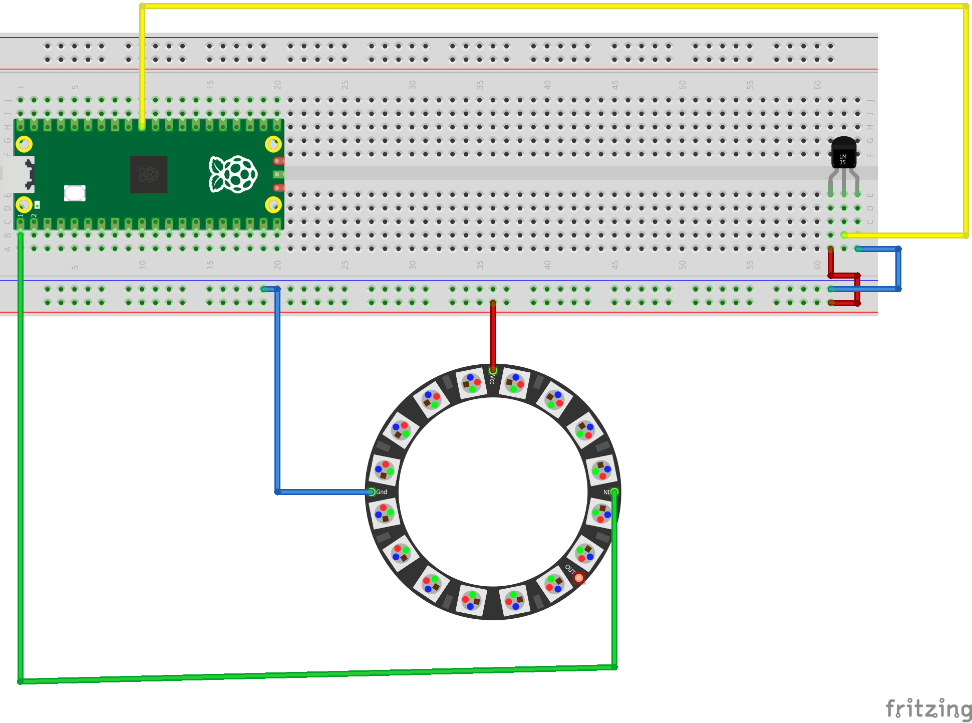
Step 1: Wiring the ComponentsThe wiring schematic is straightforward and lacks complexity.
- Connect the power (Red) and Ground (Black) wires of the NeoPixel and LM35 to the appropriate 5V and GND pins on the Raspberry Pi Pico.
- The analog signal (Brown) from the LM35 connects to ADC 0 on the Pico.
- The digital input (Green) of the NeoPixel connects to GPIO 0 on the Pico.
(Note: A high-resolution schematic image should be provided here.)
Installing the sensors requires careful placement inside the console to accurately monitor temperature and ensure the LEDs are visible.
A. Installing the LM35 Sensor- Carefully remove the PS5’s white outer plates and unscrew the black inner casing.
- Locate the APU (CPU/GPU combined processor). Since this area generates the most heat when the system is under heavy load, the LM35 should be placed nearby.
- Affix the LM35 using double-sided tape near the APU.
- Crucial Safety Tip: Ensure the three pins of the LM35 sensor do not directly contact the metallic heatsink. Using double-sided tape helps prevent a short circuit between the positive and negative pins.
- Route the three wires (Positive, GND, Analog Signal) through the back casing of the PS5.
- Place the 16-LED NeoPixel ring on the back internal casing. (Note: Initial placement may need adjustment to ensure the white outer plates fit correctly due to depth limitations. We recommend placing it where the casing offers maximum depth.)
- Use double-sided tape to secure the NeoPixel ring so it does not move.
- Route the NeoPixel wires (Positive, Negative/GND, Digital Input) out of the casing.
Reassemble the black casing and the white plates, making sure all screws and connections (like the fan socket) are secured. The exposed wires connect to the Pico.
Step 3: Programming the Logic (MicroPython/Python)The software uses the Pico to read the analog temperature data from the LM35, convert it to Celsius, and trigger different lighting functions based on defined thresholds.
We define five key color/effect functions: set_color, wheel, rainbow, pulse, and dance.
Core Logic: Temperature ThresholdsThe code operates within an infinite loop, continuously reading the temperature (via the read_temp function) and adjusting the lighting mode accordingly.
import machine
import utime
import neopixel
import math


NUM_LEDS = 16
PIN = 0
np = neopixel.NeoPixel(machine.Pin(PIN), NUM_LEDS)


adc = machine.ADC(26)
VREF = 3.3
CONVERSION = VREF / 65535


def read_temp():
    raw = adc.read_u16()
    voltage = raw * CONVERSION
    temp_c = voltage * 100
    return temp_c


def set_color(r, g, b):
    for i in range(NUM_LEDS):
        np[i] = (r, g, b)
    np.write()


def wheel(pos):
    if pos < 85:
        return (pos * 3, 255 - pos * 3, 0)
    elif pos < 170:
        pos -= 85
        return (255 - pos * 3, 0, pos * 3)
    else:
        pos -= 170
        return (0, pos * 3, 255 - pos * 3)

def rainbow(wait=20):
    for j in range(256):
        for i in range(NUM_LEDS):
            idx = (i * 256 // NUM_LEDS) + j
            np[i] = wheel(idx & 255)
        np.write()
        utime.sleep_ms(wait)


def pulse(color=(255,0,0), steps=40, delay=20):
    r, g, b = color
    for i in range(steps):
        factor = (math.sin(i / steps * math.pi) ** 2)
        set_color(int(r*factor), int(g*factor), int(b*factor))
        utime.sleep_ms(delay)


def dance(delay=20):
    colors = [(255,0,0), (0,255,0), (0,0,255), (255,255,0)]
    steps = 50
    for c in range(len(colors)):
        r1,g1,b1 = colors[c]
        r2,g2,b2 = colors[(c+1) % len(colors)]
        for i in range(steps):
            r = int(r1 + (r2-r1) * i/steps)
            g = int(g1 + (g2-g1) * i/steps)
            b = int(b1 + (b2-b1) * i/steps)
            set_color(r,g,b)
            utime.sleep_ms(delay)


while True:
    temp = read_temp()
    print("Temp:", temp)

    if temp < 25:
        set_color(0, 0, 255)

    elif 25 <= temp < 30:
        dance(delay=30)

    elif 30 <= temp < 40:
        #pulse(color=(255,0,0))
        rainbow(wait=10)

    elif 40 <= temp < 55:
        pulse(color=(255,0,0))
        #rainbow(wait=10)
    else:
        rainbow(wait=10)
Temperature Range (Celsius)
Condition/Atmosphere
Lighting Mode / Function
Example Color/Effect
Below 25°C
Console startup, loading screens, low activity.
Cool/Calm.
Soft Blue (using set_color).
30°C to 40°C
Standard gameplay, rising load.
Rainbow (rainbow).
Cycling Colors.
Above 45°C
High processing load, intense action scenes (e.g., heavy combat).
Exciting/Action.
Pulsing Red (pulse).
This temperature mapping connects the system's processing burden to the ambient lighting. When the temperature rises, it signals that the console has entered an intensive scene, and the lighting changes to an exciting effect.
(Note: The full code script containing initialization, the read_temp function, and the loop logic should be provided here.)
Step 4: Testing and CalibrationThe final step is connecting the components via a breadboard (for testing) and running the code. We power the circuit using a 5V DC supply.
During testing with a game like Spider-Man:
- At startup, the temperature was low (below 30°C).
- As the game began, the temperature rose above 30°C (e.g., 30.7°C, then 31°C), triggering the Rainbow mode.
- When gameplay continued and the processing load increased further (e.g., entering crowded or complex environments), the temperature exceeded 45°C, which immediately initiated the Pulsing Red mode. This pulsating light indicates a state of high stress and action on the console.
Calibration Note: Temperature thresholds need to be fine-tuned (trial and error) based on the specific game being played, as games like Call of Duty may put a high load on the processor right from the start (requiring higher starting thresholds), while open-world games like Red Dead Redemption may see temperature rise more gradually.
Conclusion and Future EnhancementsThis project successfully integrates a low-cost LM35 temperature sensor with a Raspberry Pi Pico 2 to create dynamic RGB lighting for the PS5, enhancing immersion during intense gaming sessions.
While this method provides a simple and effective solution, it’s important to note the primary limitation: the LM35 sensor is inexpensive and reacts slowly to instantaneous changes. If a player rapidly enters an action scene (like in Spider-Man combat), the console temperature and, consequently, the light change might be slightly delayed.
Future upgrades for greater accuracy and instant response could involve:
- Using more accurate/faster temperature sensors.
- Implementing image processing (analyzing screen capture) to directly match the RGB output to the visual atmosphere of the game, although this requires significantly more complex hardware and programming.
We hope you enjoyed this initial phase of our smart lighting project! Feel free to share your calibrations and results in the comments below.


Comments