

Hardware components | ||||||
| × | 1 | ||||
Software apps and online services | ||||||
| ||||||
| ||||||
| ||||||
 |
| |||||
Hello everybody.
It's been a long time since I've found time to write a tutorial. But now I'm back in business, so bare with me, read the tutorial and you'll be rewarded with a nice project and a temperature controller.
Since I'm fan of the IoT I'm always looking for new hardware. So after testing a lot of boards (Raspberry Pi, Banana Pi, Beagle Bone, Arduino etc.) a friend of mine sent me link with an unknown board (at least for me): Linkit Smart Duo. I read the manufacturer description and I was convinced to give it a try and I wasn't disappointed.
As I said I was amazed how easy is to work with this little device. Since I don't like messing with wires I designed a PCB for making a permanent project.
A friend of mine needed a temperature controller and I said to myself that will be a good oportunity to make a standalone device. The result is presented below:
Blynk Interface...
The interface consists of 3 Tabs: Dashboard, Termperature Control, and Log.
Here the controls are self explanatory.
This is the temperature control tab. The Setpoint Low slider selects the minimum temperature.
The Hysteresis slider selects the difference between the min and max temperature.
Setpoint High is the sum of Setpoint Low value and Hysteresis value.
Now, you have two dropdown controls one is Mode and another is Control. With Mode you can select if the controller it's used for heating or cooling. When in Cooling mode the device will wait until the Setpoint High temperature will be reached. In that moment it will send a command to the relay that is controlling the cooler and the cooler will be turned on. It will stay on until the Setpoint Low temperature will be reached. And the cycle will go on.
In Heating mode the device will wait until Setpoint Low temperature will be reached. From that moment the heater will be turned on and it will stay on until Setpoint High temperature will be reached.
For this to happen the selected Mode must be "Automated". When this mode is active the device will ignore all the commands sent manually (by pushing "T. Controller" button). To control the device manually you will have to switch on Manual control.
Last but not least I used a Graph which will record the temperature and the working cycles of the controller.
The last tab is the Log:
The hardware...
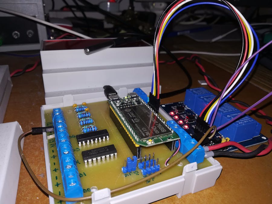
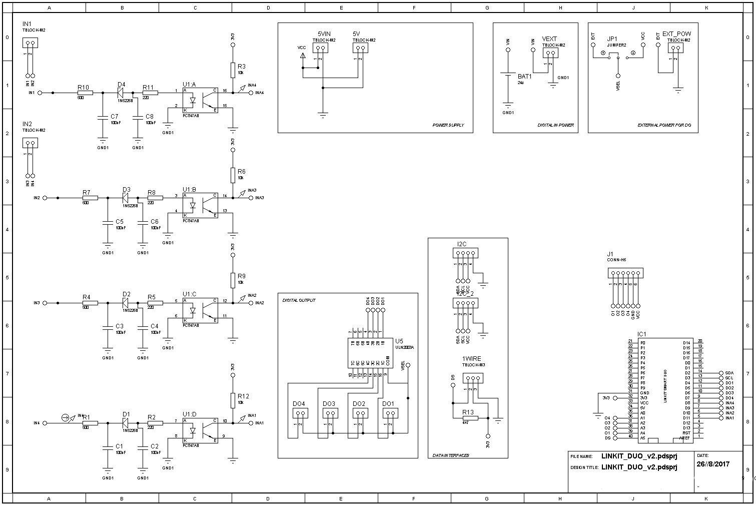
As I said I designed a PCB which (hopefully) keeps everything in one place. What I manged to achieve is:
- 4 isolated digital inputs that can accept voltages from 0 to 24V;
- 4 digital inputs/outputs connected directly to MCU pins. They can supply 3.3V when are set as outputs and can read 3.3V max when set as inputs;
- 4 digital outputs connected to an ULN2003 chip. They can be used for driving small loads like relays, dc motors and one bipolar stepper motor. The voltage supply of ULN 2003 can be selected through a jumper. You can supply 5V(the voltage of the board) but also up to 36 V by applying voltage on EXT_POW connector;
- 1x I2C header for various devices that are using this protocol.
- 1x 1Wire screw terminal for connecting the famous 1wire sensor DS18B20.
The PCB is placed in a small case that can be mounted on DIN rail. Because of the space available I decided to use an external board with 4 relays.
Note: Because the relays are turned on when digital output is 0 the logic is reversed. Please take this into account if you want to modify the code.
And now pictures!
Getting started...
I will not insist on describing the Linkit Duo because you can find all the information on official page .
If this is your first contact with this board before going any further be sure that you followed the tutorials listed on the official page:
- Sign in to your new board : Note: if you can't acces http://mylinkit.local you should try to connect directly to the board by typing into the brwoser the folloing address http://192.168.100.1
- Install Arduino with Linkit Smart support.
- Install the ComPort driver.
Fortunately you will have to do all these steps only once.
The next step it's to find the local ip address that your router assigned to your device. To find the address I used a piece of software called Angry IP Scanner. You can download it from here. After you will scan your network you will get something like this:
Now that you know Linkit Duo local IP address it's time to access it using secure shell, in short SSH. For this i used Putty. So download Putty from here, enter your IP address and type in the user (root) and password that you set on first step.
As you can see Linkit Duo it's running a linux distro called OpenWrt. So you can enjoy all the benefits that an OS has, though OpenWrt it's not the most friendly distro.
Now take a deeep breath and proceed to the next step. Since the device has only 32 MB available for storage, with limited read/write cycle you'll wand to mount the file system on a SD card. This is very important. For this you'll have to read the tutorial listed here.
One more step and we are done. Because I want to make things simple for accessing and editing files on Linkit I use a dedicated software called WinSCP. So download and install this piece of software. After installing, login to your Linkit device using the Secure Copy Protocol (SCP):
After a successful login you will have access to Linkit files easy:
At this moment we have the hardware ready. Horrrayyy !! :)
The software...
Now that we installed everything and we have access to the device file system it's time to write the software for making things happen.
As you already know the Linkit Smart Duo consists of a MT7688 Mediatek processor and a ATmega32U4 MCU, more or less an Arduino Mini. The processor and the microcontroller are linked via a virtual bridge like the one it's used for Arduino Yun. If you want to read more please read the Yun documentation on Arduino website. Because the MCU has limited capabilities (8MHz, 32KB ROM) and the project it's pretty complex I decided to split the "job" in two:
- The MCU will be responsible for reading sensors and control the hardware;
- The MPU will deal with the Blynk server by sending the status of the sensors and reading the commands.
That being said we have to write two programs: one for ATmega32U4 (Arduino) and one that will deal with Blynk server (Node JS).
In code section you will find the Arduino side program. It makes use of 3 libraries:
- Tasker - for scheduling tasks (more like timer trigger)
- OneWire and DallasTemperature - for dealing with the temperature sensor DS18B20;
As you can see there is no code in loop(). That's because Tasker will take care of everything.
Note: Please read the code comments.
So download the sketch and upload to the microcontroller.
Now login with WinSCP to your device and inside root direcory create a folder called "apps" inside this folder create another called "node" and finally inside of the last created folder (or directory :) ) create a folder named "blynk".
Inside this folder create an empty file and name it app.js. Copy/paste the Node Js code inside and you're done.
The last step is to install the node js libraries inside this folder. For this task ssh your device with Putty and go to your blynk folder by typing:
cd apps/node/blynk
Now that you are inside this folder we have to install the blynk and serialport libraries:
npm install serialport@4.0.7
npm install blynk-library
Installing serialport it will take forever, so be patient :) !
After everything is in place you will have to run the program:
node apps/node/blynk/app.js
The easiest part is to use Blynk. For this, download the app either for IoS either for Android create an account and scan the QR code below. Blynk is free. But you will only get 2000 credits when the project is started. This project is made with 6400 credits so you will need to buy 5000 credits more. Don't worry it's cheap only 3.99$.
That's it !
Good luck.


Comments