Meeker6751
Published © GPL3+

Arduino Oscilloscope (6-Channel)

Standalone Arduino 6-channel triggered oscilloscope with optional freeze frame.

BeginnerProtip76,502
Arduino Oscilloscope (6-Channel)

Things used in this project

Story

Read more

Schematics

6 Channel Oscilloscope

Code

Oscilloscope.ino

C/C++
/*
  File:  Oscilloscope.ino
  Title:  Standalone Arduino 6 channel Triggered Oscilloscope
  Author: Meeker6751
  Verson: 2018.4.23

  Method: (0) Set the adjustable variables, (1) run the sketch (2) activate the serial plotter.

  Description: This sketch simulates a 6 beam oscilloscope.  It is expected that the input(s) presented at the analog pins will be between
  0 and 5 volts with a maximum frequency of 1 KHz.  The adjustable variables are declared in a separate section.  These variables can be
  found after the define statements. 1-6 beams may be selected which display voltages at A0-A5, respectively.  Open analog pins produce
  spurious voltages.

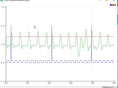
  The oscilloscope runs in 2 modes: 'continuous' (free running) and 'triggered' (start sweep when a criterion is met.  The triggering
  criterion is met when the input signal read off od A0 crosses over a predefined triggering voltage.  The criterion is further
  conditioned by whether it is 'rising' or 'falling' when it crosses the predefined voltage.  In triggered mode the total sweep time
  may be set in milliseconds. The beginning of a triggered sweep is indicated when the timing mark spikes to 5 vdc.

  When sweeping, the analog pin(s) will be sampled every 'SampleInterval' milliseconds.  At the  bottom of the plot, timing marks
  (a square wave) will be toggled every 10th 'SampleInterval' milliseconds.

  When more than 1 signal is being sampled, the signal displays may be 'superimposed' or 'channeled'.  When channels are used, the
  voltages on the vertical axis are not  calibrated.

  The builtin LED (pin 13) is an indicator of the oscilloscope state: (1) On, continuous mode or sweeping in triggered mode;
  (2) blinking, Armed in triggered mode, (3) Off, all operations paused (by push button).

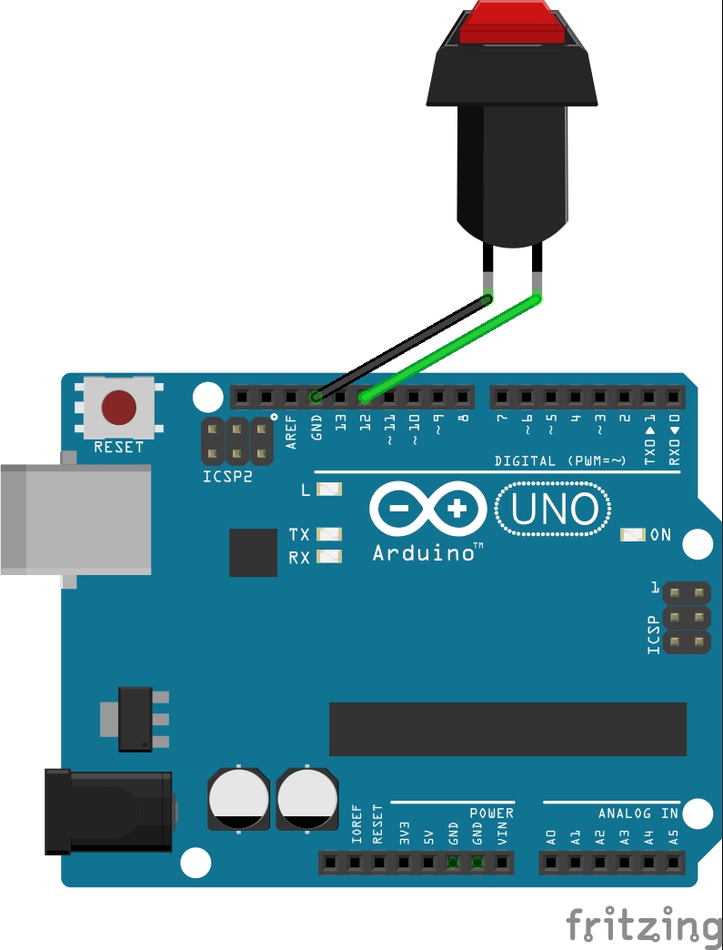
  Optionally a push button, can be connected to ground and digital pin 12.  When pressed, signal sampling and sweep are stopped.
  Pressing the push button again resumes the sweep (but with a gap in the signal trace(s)).

  The order of the plotted line legend is: timing marks (blue), trigger level (red, if in triggered mode), analog signals A0-A6,
  respectively (multi colored).
*/

#define ul unsigned long
#define armed true                                                       // trigger and pushbutton state
#define continuous true                                                  // sweep mode (free running)
#define falling false                                                    // trigger slope positive
#define rising true                                                      // trigger slope negative
#define triggered false                                                  // sweep mode (sweep starts when triggered)
#define sweeping false                                                   // sweeping for TriggeredSweepInterval msecs
#define superimposed true                                                // signals superimposed on display
#define channeled false                                                  // signals channeled on display

// adjustable variables
int   Beams = 6;                                                         // number of beams read
bool  DisplayMode = channeled;                                           // 'superimposed' or 'channeled'
ul    SampleInterval = 200;                                              // units: msecs * 10; 0.1 <= SampleInterval
bool  SweepMode = triggered;                                             // 'continuous' or 'triggered'
ul    TriggeredSweepInterval = 40000;                                    // total sweep time, units: seconds * 10,000
float TriggerDirection = rising;                                         // 'rising' or 'falling'
float TriggerVolts = 3.5;                                                // trigger vdc; 0 <= TriggerVolts <= 5

// interrupt controlled variables
ul    LastSample = -1;                                                   // initially, no last sample
bool  LED = HIGH;
int   BlinkCount = 0;
ul    SweepCount = 0;                                                    // counts up to Sweep Interval
bool  Tick = false;                                                      // set to true when TickCount = SampleRate
ul    TickCount = 0;                                                     // counts up to SampleRate
bool  TimingMark;                                                        // toggles every 10th 'Sample Intewrval'
ul    TimingMarkCount = 0;                                               // counts up to SampleInterval * 10
bool  TriggerState;                                                      // 'armed' or 'sweeping'
bool  TriggerOnset = false;                                              // marks first tick after trigger occurs

// loop procedure variables
float ChannelFloor;
float ChannelHeight;
bool  freeze = false;                                                    // true: stop; false: run
int   PBPin = 12;                                                        // grounded push button on pin 12 (optional)
int   PBLastState = HIGH;                                                // LOW (pressed) or HIGH (released)
int   PBVal;                                                             // inverse logic, push button tied to ground
float ChannelScale;                                                      // proportion og signal to display
float TriggerDisplay;                                                    // vertical position of trigger
int   TriggerLevel;                                                      // calculated from 'TriggerVolts'
float Value;

void interruptSetup() {
  noInterrupts();                                                        // generate an interrupt every 0.1 msec
  TCCR2A = 2;                                                            // clear timer on compare, OCR2
  TCCR2B = 2;                                                            // 16,000,000Hz/8=2,000,000 Hz; T2 clock ticks every 0.0005 msecs
  OCR2A = 199;                                                           // interrupt = 0.0005*200 = 0.1 msec
  TIMSK2 = 2;                                                            // set the ISR COMPA vect
  interrupts();
}

ISR(TIMER2_COMPA_vect) {                                                 // interrupt every 0.1 msecs
  if (TickCount < SampleInterval) {
    TickCount++;
    BlinkCount++;
    if (BlinkCount >= 500) {
      BlinkCount = 0.0;
      LED = !LED;                                                         // toggle LED every 50 msecs
    }
  }
  else {                                                                 // 'SampleInterval' has elapsed
    Tick = true;
    TickCount = 0;
    TimingMarkCount++;                                                   // update Timing mark
    if (TimingMarkCount >= 10) {                                         // 10th 'SDampleInterval' has occurred
      TimingMark = !TimingMark;
      TimingMarkCount = 0;
    }
    if (SweepMode == triggered) {
      if (TriggerState == sweeping) {                                    // sweeping, update sweep time
        SweepCount +=  SampleInterval;
        if (SweepCount >= TriggeredSweepInterval) {                      // sweep complete
          TriggerState = armed;
          LastSample = -1;
        }
      }
      else {                                                            // armed, look for trigger
        Value = analogRead(A0);
        if (LastSample > 0 and
            ((TriggerDirection == rising and Value >= TriggerLevel and LastSample < TriggerLevel) or
             (TriggerDirection == falling and Value <= TriggerLevel and LastSample > TriggerLevel))) {
          TriggerState = sweeping;                                     // triggered
          SweepCount = 0;
          TriggerOnset = true;
          TimingMarkCount = 0;
          TimingMark = true;
        }
        LastSample = Value;
      }
    }
  }
}

void setup() {
  pinMode (LED_BUILTIN, OUTPUT);
  pinMode(PBPin, INPUT);                                                 // connected to a grounded push button
  digitalWrite(PBPin, HIGH);                                             // pullup push button pin
  Serial.begin(115200);
  if (SweepMode == continuous) {
    TriggerState = sweeping;
  }
  else {
    TriggerState = armed;
  }
  TriggerLevel = (TriggerVolts / 5.0 ) * 1023;
  ChannelHeight = 5.0 / Beams;
  ChannelScale = 5.0 / 1024.0 / Beams;
  TriggerDisplay = TriggerVolts * ChannelScale + 5.0 - ChannelHeight;
  interruptSetup();
}

void loop() {
  if (freeze) {
    digitalWrite(LED_BUILTIN, LOW);
  }
  else if (TriggerState == armed) {
    digitalWrite(LED_BUILTIN, LED);
  }
  else  {
    digitalWrite(LED_BUILTIN, HIGH);
  }
  PBVal = digitalRead(PBPin);
  if (PBVal == LOW and PBLastState == HIGH) {                            // falling edge
    freeze = !freeze;
    delay (2);                                                           // ignore contact bounce
  }
  PBLastState = PBVal;
  if  (!freeze and TriggerState  == sweeping) {
    if (Tick) {                                                          // sample if Sample Interval msecs have elapsed
      if (TimingMark) {                                                  // display timing marks and trigger, if present
        if (TriggerOnset) {
          Serial.print(5.0);
          TriggerOnset = false;
        }
        else {
          Serial.print(0.1);
        }
      }
      else {
        Serial.print(0.0);
      }
      Serial.print(" ");
      ChannelFloor = 5.0 - ChannelHeight;                                // display trigger level, if applicable
      if (SweepMode == triggered) {
        Serial.print(TriggerLevel * ChannelScale + ChannelFloor);
        Serial.print (" ");
      }
      for (int AnalogPin = 0; AnalogPin <= Beams - 1; AnalogPin++) {     // sample 1-6 analog signals and display them
        Value = analogRead(AnalogPin);
        Value = Value * ChannelScale + ChannelFloor;
        Serial.print(Value);
        Serial.print(" ");
        ChannelFloor -= ChannelHeight;
      }
      Tick = false;
      Serial.println("");
    }
  }
}

Credits

Meeker6751

Meeker6751

1 project • 41 followers

Comments