


Hardware components | ||||||
| × | 4 | ||||
| × | 3 | ||||
| × | 1 | ||||
 |
| × | 1 | |||
 |
| × | 1 | |||
Software apps and online services | ||||||
 |
| |||||
 |
| |||||
Hand tools and fabrication machines | ||||||
 |
| |||||
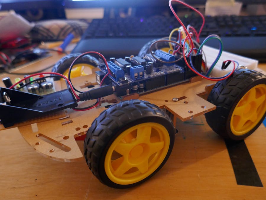
I've always wondered what it took to make a self-driving car. So for my first program, I decided to try it. The car follows the blue line, and when one of the sensor sees red, it makes a curve in the opposite direction.
The plate on the back of the car is where I have theb battery with a battery overwatch.
The Chassis was purchased from the Internet, but it does not have to be this one.
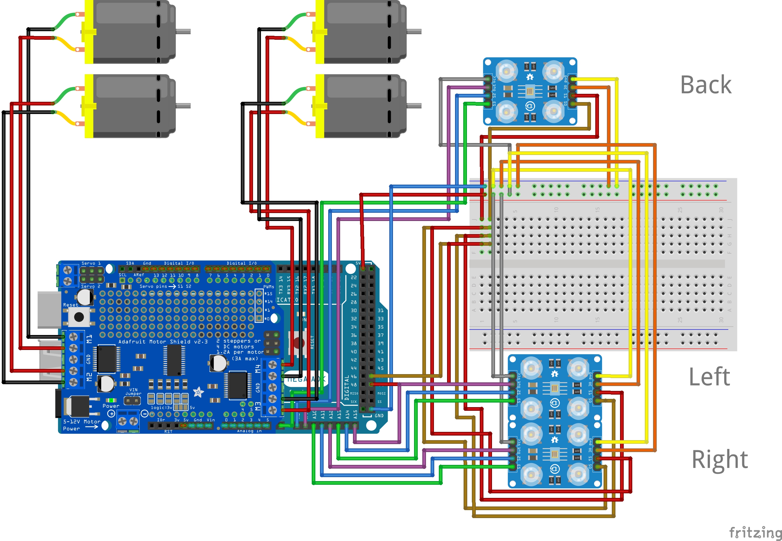
Explination of the Program:1. Definition:1.1 Motor:
#include<AFMotor.h>
AF_DCMotormotor1(1, MOTOR12_1KHZ);
AF_DCMotormotor2(3, MOTOR34_1KHZ);
AF_DCMotormotor3(2, MOTOR12_1KHZ);
AF_DCMotormotor4(4, MOTOR34_1KHZ);
First line is the Inclution of the AFMotor library. Lines 2-4 is the definition of the diffrent Motors.
1.2 Color Sensor:
const int s0 = A8; //Conection for Sensor
const int s1 = A9;
const int s2L = A11; //Left Sensor
const int s3L = A10;
const int outL = A12;
int redL =0;
int greenL= 0;
int blueL =0;
const int s2R = A14;  //Right Sensor
const int s3R = A13;
const int outR = A15;
int redR =0;
int greenR= 0;
int blueR =0;
"A9" and "A8" are the outputs for the General Light of the Colorsensor.
"s2" and "s3" are the inputs of the sensor each sensor has such an port. The letter on the end is for the Location. L is for Left and R is for Right.
out is the frequenty output of the Sensor also left and right. See more info here.
The variable for the colors Red, Blue and Green are also two times at hand the diffrents is also the last letter L and R.
1.3 Detection:
int sensor_left = 0;
int sensor_right = 0;
Those two variables are for the case when the Car sees the the Color it shoud follow. More to that later.
2. Set up:Now follows the "void Setpup()"
2.1 Serial Kommunitaktion
Fist thing is we activate the Serial Komunikation.
Serial.begin(9600); //Serielle Kommunikation
2.2 Color Sensor:
The Color Sensor has some outputs. The common outputs Are "s0" and "s1".
pinMode(s0, OUTPUT);
pinMode(s1, OUTPUT);
digitalWrite(s0, HIGH);
digitalWrite(s1, HIGH);
The fist two Lines set the Pins "s1" and "s0" to output mode.
The two last lines set the Output to High that the LED are allways on.
pinMode(s2L, OUTPUT);
pinMode(s3L, OUTPUT);
pinMode(outL, INPUT);
pinMode(s2R, OUTPUT);
pinMode(s3R, OUTPUT);
pinMode(outR, INPUT);
Now we set up the other pins the "s2" and "s3" must be set to output mode and the "out" pins must be set to input.
3. Main ProgramNow comes the main part.
3.1 Activate Function Color
The first thing is the activation of the function color. This function will be defined at the end of the Program.
color();
Here we wil program the detection part of the prgoram. The part that look if the Road is beneath the Car. We will do that with an easy "If" function.
if(blueL <= 10 && redL >=11 && greenL >= 11 && blueL < redL && blueL <greenL)
{
sensor_left = 1;
}
else
{
sensor_left = 0;
}
}
So that the variable "sensor_left" to an High Signal switches. The following condiction must be met.
- The variable "blueL" must have a lower or even value of 10.
- The variable "redL" and greenL" must have a higher or even value of 11.
- Also "blueL" must be smaller than "redL" and "greenL".
Or else the variables "sensor_left" will go to 0.
The code for the Right sensor is Identical, the only diffrents is "L" and the "left". there then must be a "R" and "right" for the other Sensor.
3.3 DrivingNow comes the most important part of the program. The driving part.
The car is programmed to drive "staighthead" if both sensors in the front see blue and when only one of them sees blue it will turn the opposite direction. But if only the Sensor in the back sees blue it will go backwards.


Comments