


Hardware components | ||||||
| × | 1 | ||||
_ztBMuBhMHo.jpg?auto=compress%2Cformat&w=48&h=48&fit=fill&bg=ffffff) |
| × | 1 | |||
| × | 1 | ||||
 |
| × | 1 | |||
 |
| × | 1 | |||
| × | 1 | ||||
| × | 1 | ||||
 |
| × | 1 | |||
| × | 1 | ||||
Software apps and online services | ||||||
| ||||||
 |
| |||||
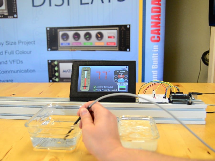
This project builds upon our previous Stage 1 GTT Thermometer demo. We've implemented 4 additional buttons, and 2 dynamic labels to create an interactive HMI for setting high and low temperature limits. The Arduino will continually take readings and update the GTT's bar graph and label. If the temperature exceeds either of the two limits, the GTT's piezo buzzer and feedback motor will be activated to alert the user.
Hardware- GTT Series Intelligent TFT Display
- Arduino Uno
- Breadboard
- Male-to-male Jumper cables
- 4.7k Ohm resistor
- DS18S20 Temperature Sensor
- 4pin Bread Board cable
- USB to Mini-USB cable
- Power Adapter (optional)
- GTT GUI Designer Software
- Arduino IDE
Our previous GTT Designer project was modified for this demo. Two labels are implemented to display the high and low temperature limits. Four buttons add control, allowing users to manually set the high and low temperature limits. Each button label has been changed to a '+' or '-' to indicate their function appropriately.
The bar graph, indicator toggles, and current temperature label that were implemented in the previous stage are still present here.
You can download our free and fast GUI design software here
The project files can be downloaded here
Once the design is completed, the project can be deployed to the GTT. You'll need to connect your PC to the GTT's Mass Storage header, and hit "Deploy" in the GTT Designer. All the necessary files will be generated and deployed directly to the display.
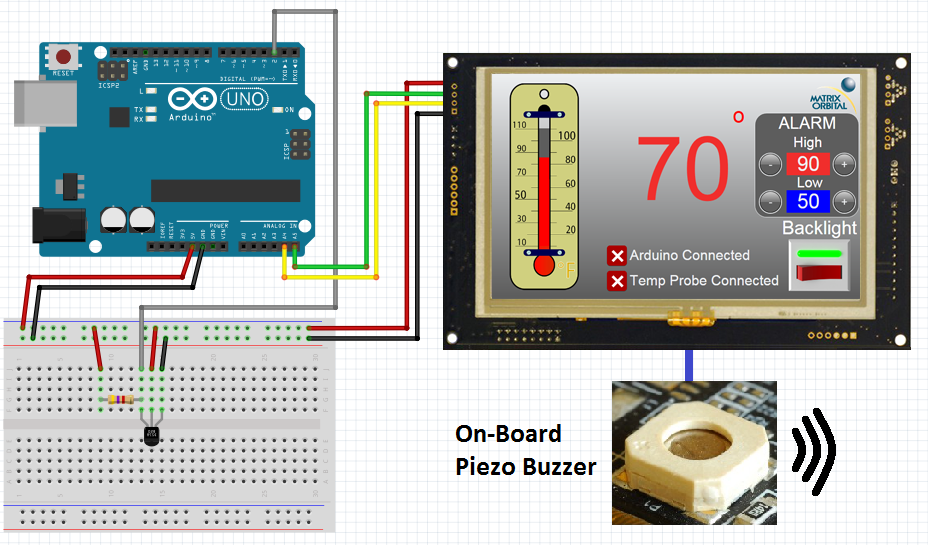
Step 2: Connecting the GTTSimilar to our Stage 1 demo, we'll continue to use I2C to communicate between the Arduino Uno and the GTT. Using the Bread Board Cable, connect the 4 pin header to the GTT's I2C header. Then connect the Red Bread Board Cable lead to 5V power, and connect the Black lead to ground. The Yellow (SDA) and Green (SCL) leads need to be connected to the Arduino Uno's SDA pin (A4) and SCL pin (A5) respectively. No I2C pull-up resistors are required for communication with the GTT. Additional power can be applied through the displays barrel jack.
Step 3: Connecting the DS18S20A 4.7k Ohm pull-up resistor must be placed in parallel with the D18S20's power and data pins, otherwise the sensor will be unable to communicate properly. The data pin can be connected to any digital pin on the Arduino; in this case we selected pin 2.
Before continuing, download and unzip the the following GTT Client Libraries. These libraries can also be found within the most recent GTT Firmware release. Once downloaded, copy over the contents of GttClient into \Users\YourUserName\Documents\Arduino\libraries\gtt. GTT Client Library
The OneWire library will also be required for this demo. You can install the OneWire library through the Aduino IDE Library Manager.
Step 5: Code//GTT Arduino Thermometer Demo Stage 2
//Arduino Uno with Matrix Orbital GTT70A and DS18S20
//Created by Divino, 24/04/2018
//support@matrixorbital.ca
//www.matrixorbital.ca/appnotes
#include <gtt.h>
#include <gtt_device.h>
#include <gtt_enum.h>
#include <gtt_events.h>
#include <gtt_ext_types.h>
#include <gtt_packet_builder.h>
#include <gtt_parser.h>
#include <gtt_protocol.h>
#include <gtt_text.h>
#include <Wire.h>
#include <OneWire.h>
#include "GTT_Arduino_Thermometer_Demo_Stage_2.c"
#include "GTT_Arduino_Thermometer_Demo_Stage_2.h"
#include <stdlib.h>
#define I2C_Address 0x28 //Define default 8bit I2C address of 0x50 >> 1 for 7bit Arduino
OneWire ds18s20(2); //sensor on pin 2
gtt_device gtt; //Declare the GTT device
byte addr[8]; //Buffer to store One wire Address
bool probeConnected; //Bool to determine indicate if the DS18S20 is connected
bool tempSensorReady = 1;
uint8_t maxTemp = 90; //Default Max limit
uint8_t minTemp = 60; //Default Low limit
unsigned long tempTimer;
// Buffer for incoming data
uint8_t rx_buffer[64] = {0};
// Buffer for outgoing data
uint8_t tx_buffer[64] = {0};
void setup() {
//Setup I2C bus
gtt.Write = i2cWrite; //Set the write function
gtt.Read = i2cRead; //Set the read function
gtt.rx_buffer = rx_buffer; //Declare a buffer for input data
gtt.rx_buffer_size = sizeof(rx_buffer); //Declare the size of the input buffer
gtt.tx_buffer = tx_buffer; //Declare a buffer for output data
gtt.tx_buffer_size = sizeof(tx_buffer); //Declare the size of the output buffer
Wire.begin(); //Begin I2C communication
Serial.begin(9600);
delay(100);
resetDisplay();
//Wait for display to reset
delay(3000);
gtt_set_screen1_image_toggle_2_state(>t, 1); //If the Arduino can establish communication with the GTT, toggle the Arduino connection indicator appropriately
gtt25_set_button_clickhandler(>t, MyButtonClick); //Configure the button click handler
setCommunicationChannel(2); //set the communication channel to i2c so button clicks can be returned to the Arduino
tempSensorReady = 1; //Indicate that the DS18S20 is ready for communication
}
void loop() {
if(tempSensorReady){ //If the DS18S20 is ready to start a conversion
probeConnected = searchForTempProbe(); //Search for the DS18S20
startTempConversion(); //Start the temperature sensor reading process
tempTimer = millis(); //Start conversion timer
tempSensorReady = 0; //Toggle SensorReady bool
}
if((millis()-tempTimer)>=800){ //800+ mS after starting the conversion, read the temp
if(probeConnected){ //If the probe is connected
int16_t temp = readTempProbe(); //Read the temperature
char buf[4] = {0};
sprintf(buf,"%d",temp); //Convert the temperature value to a string
gtt_set_screen1_dynamic_label_2_text(>t, gtt_make_text_ascii(buf)); //Update the GTT label
gtt_set_screen1_bar_graph_1_value(>t, temp); //Update the GTT bar graph
//If the temperature exceeds either the high or low limit, activate the buzzer and motor
if(temp >= maxTemp){
Serial.println("Buzzing High");
activateBuzzerAndMotor(1000, 500);
}
if(temp <= minTemp){
Serial.println("Buzzing low");
activateBuzzerAndMotor(500, 500);
}
}
else { //If the probe isn't connected
gtt_set_screen1_image_toggle_3_state(>t, 0); //Set the probe indicator to "Disconnected"
gtt_set_screen1_bar_graph_1_value(>t, 0); //Set the GTT bar graph to 0
gtt_set_screen1_dynamic_label_2_text(>t, gtt_make_text_ascii("NA")); //Update the GTT label to "NA"
}
tempSensorReady = 1; //Temperature sensor is ready for another conversion
}
gtt_parser_process(>t); //Parse for touch events
}
void MyButtonClick(gtt_device* gtt, uint16_t ObjectID, uint8_t State)
{
Serial.println(State);
if (State == 1)
{
char buf[4] = {0};
if (ObjectID == id_screen1_circle_button_1)
{
if((maxTemp-1)>minTemp){
maxTemp--;
Serial.print("maxTemp = ");
Serial.println(maxTemp);
sprintf(buf,"%d",maxTemp); //Convert the temperature value to a string
gtt_set_screen1_dynamic_label_3_text(gtt, gtt_make_text_ascii(buf)); //Update the High limit
}
}
if (ObjectID == id_screen1_circle_button_2)
{
if(minTemp >0)
{
minTemp--;
Serial.print("minTemp = ");
Serial.println(minTemp);
sprintf(buf,"%d",minTemp); //Convert the temperature value to a string
gtt_set_screen1_dynamic_label_1_text(gtt, gtt_make_text_ascii(buf)); //Update the Low limit
}
}
if (ObjectID == id_screen1_circle_button_3)
{
if(maxTemp <110)
{
maxTemp++;
Serial.print("maxTemp = ");
Serial.println(maxTemp);
sprintf(buf,"%d",maxTemp); //Convert the temperature value to a string
gtt_set_screen1_dynamic_label_3_text(gtt, gtt_make_text_ascii(buf)); //Update the High limit
}
}
if (ObjectID == id_screen1_circle_button_4)
{
if((minTemp+1)<maxTemp)
{
minTemp++;
Serial.print("minTemp = ");
Serial.println(minTemp);
sprintf(buf,"%d",minTemp); //Convert the temperature value to a string
gtt_set_screen1_dynamic_label_1_text(gtt, gtt_make_text_ascii(buf)); //Update the Low limit
}
}
}
}
void resetDisplay() {
Serial.println("resetting display");
char command[] = { 254, 1 };
i2cWrite(>t, command, sizeof(command));
}
void setCommunicationChannel(byte channel) {
Serial.println("Setting Communication Channel");
char command[] = { 254, 5, channel };
i2cWrite(>t, command, sizeof(command));
}
void activateBuzzerAndMotor(short frequency, short duration) {
Serial.println("Setting Communication Channel");
char command[] = { 254, 183, (byte)(frequency >>8), (byte)(frequency && 0xFF), (byte)(duration >>8), (byte)(duration && 0xFF)};
i2cWrite(>t, command, sizeof(command));
}
/* The Code used in the searchorTempProbe and readTempProbe function is
* sample code taken from https://playground.arduino.cc/Learning/OneWire */
byte searchForTempProbe(){
ds18s20.reset_search();
if ( !ds18s20.search(addr)) {
Serial.print("No more addresses.\n");
ds18s20.reset_search();
delay(250);
return 0;
}
if ( OneWire::crc8( addr, 7) != addr[7]) {
Serial.print("CRC is not valid!\n");
gtt_set_screen1_image_toggle_3_state(>t, 0); //Set the probe indicator to "Disconnected"
return 0;
}
if ( addr[0] == 0x10) {
Serial.print("Device is a DS18S20 family device.\n");
gtt_set_screen1_image_toggle_3_state(>t, 1); //Set the probe indicator to "Connected"
return 1;
}
else {
Serial.print("Device family is not recognized: 0x");
Serial.println(addr[0],HEX);
gtt_set_screen1_image_toggle_3_state(>t, 0); //Set the probe indicator to "Disconnected"
return 0;
}
}
void startTempConversion(){
ds18s20.reset();
ds18s20.select(addr);
ds18s20.write(0x44,1);// start conversion, with parasite power on at the end
}
uint16_t readTempProbe(){
byte present = 0;
byte data[12];
uint16_t temp;
present = ds18s20.reset();
ds18s20.select(addr);
ds18s20.write(0xBE);// Read Scratchpad
for ( byte i = 0; i < 9; i++) {// we need 9 bytes
data[i] = ds18s20.read();
}
temp = ( (data[1] << 8) + data[0] ) * 0.5;
temp= (temp * 9/5) + 32;
Serial.print("Temp = ");
Serial.println(temp);
return temp;
}
int i2cWrite(gtt_device* gtt_device, char* data, byte data_length) {//Write an array of bytes over i2c
Wire.beginTransmission(I2C_Address);
for (int i = 0; i < data_length; i++) {
Wire.write(data[i]);
}
Wire.endTransmission();
return 0;
}
byte i2cRead(gtt_device* gtt_device) { //Wait for one byte to be read over i2c
byte data;
Wire.beginTransmission(I2C_Address);
Wire.requestFrom(I2C_Address, 1);
if(Wire.available()<1)
{
return -1;
}
else{
data = Wire.read();
return data;
}
}
Download the GTT_Arduino_Thermometer_Demo.ino file. Navigate to the GTT Arduino Thermometer Demo Stage 2 GTT files>Output folder, and grab the.c and.h files generated by the GTT Designer Suite. Place both files in the GTT_Arduino_Thermometer_Demo_Stage_2.ino source directory, then open the.ino file.
If everything is setup properly, the.c and.h file will open along with the GTT_Arduino_Thermometer_Demo.ino code.From there, you can upload the program to the Uno. The GTT will reset immediately after the program is uploaded. After a few seconds, the Thermometer demo screen will be displayed on the GTT. The image toggles will be set, indicating the connection status of the Arduino and the DS18S20 probe. If the probe becomes disconnected at any point, the indicators will provide visual notification that no temperature probe can be found.
The high and low limits default to 90°f and 60°f respectively. The high and low limits can be manually set by the operator by pressing the '+' and '-' buttons.


Comments