

Hardware components | ||||||
| × | 1 | ||||
| × | 1 | ||||
 |
| × | 1 | |||
Software apps and online services | ||||||
 |
| |||||
 |
| |||||
Hand tools and fabrication machines | ||||||
 |
| |||||
 |
| |||||
Hello,
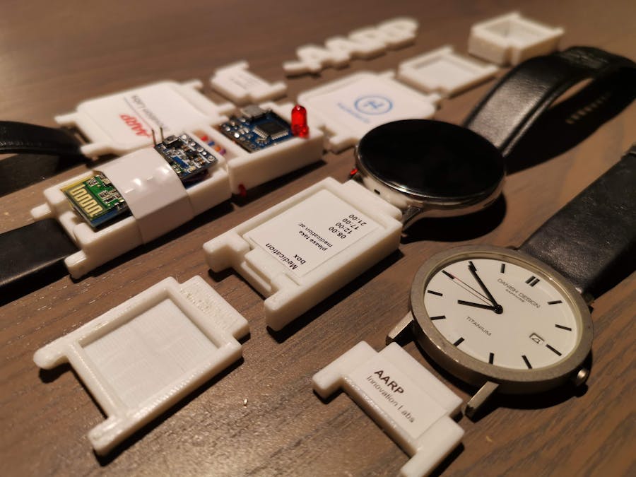
Let me introduce the ultimate (smart)bracelet for elderly people. This bracelet provides different modules that can easily be swapped. This makes that the functions of this watch optimal and personal for each person. The main module is your own module: you can wear it with the watch you have already own (this can be both an analog or digital watch) and then add smart modules in the watchband.
It can be a fall detection watch, with notifications being send to a nearby contact person. Your own watch, but with an addition medication storage, so you always have your medication with you. Or a bracelet with your personal photo and contact information.
There are endless customization options to create an ultimate bracelet or watch for everyone.
Each module has its own function. Below are all the planned modules explained. Some modules have dependencies of each other (for example, the sensor board needs the battery module).
- future moduleThe advantages of this product is that there can be modules added in the future; new designs, functionality and options can be created and installed on a later date.
Use CasesWhen you combine multiple modules, you can create different use cases. The function of the bracelet/watch will differ based on the installed modules.
Fall detectionThe wearable will automatically send an alarm to a when the person falls.
Fire/heating detectionThe wearable will automatically send an alarm when the surrounding temperature increases.
Send alarmsThe user can press the alarm button to generate an alarm that is send to a connected contact person or alarming system.
Always in contact with your personal memoriesThe build in photo frame gives you an option if you don't want a timepiece on your wrist, but have the advantages of the other smart modules on your bracelet.
Reminder to take your necessary medication on timeWear your medication/pills on your wrist so you always have them close by when you need to take them (regularly). On the module the recommended take in times can be printed, so every time you look at your watch, you're reminded that you have to take your medication.
Design / Photo braceletSince the watch itself is an option, it can also be seen as a design bracelet with your personal photo and contact information for example.
Smart braceletUse only the sensor part without the watch face to make a smart bracelet.
More information about the technical implementation can be read below.
3D printingNow let's build the wearable! To create a device, I've drawn the all the parts in Autodesk Fusion 360, printed them and put them together. Each module has its own design, but the core design of all modules are similar to each other.
All the modules are designed with the focus for comfort and modularity. In this second prototype the modules / links of the watch bracelet are 3D printed. The main advantage is that easily custom cases/parts can be created and tested.
The first prototype has the same bracelet links for each part, the end includes a metal bar where a band can be attached to. In this model a velcro band is used to make it easy to wear it (with the soft side to the skin).
All the electronics are placed on top of the bracelet modules.
If interested, you can read more about the prototype 1 hardware here. A video of the build process of the prototype hardware can be seen on Youtube here.
Prototype 2:The modules are now thinner, with inserts for the electronics so they don't stick out that much. The modules are now compatible with existing wristbands of 20mm and there are now more module designs available. This project is based on this version.
Near future plans:I've ordered more colors of 3d print filament, to make more customize options available. Also the UI on the Android application needs some improvements. (I'm not an UI developer, but it is fun to learn and develop new stuff). And I've some tweaks in mind of the module's designs, with more rounded curves. Also the pins to connect the modules, watch and band needs to be improved.
Future plans:I hope that you have in mind that I don't have a full electronic production at home, I have to make everything with the parts and tools that I have. It would be ideal to combine all the electronics into one small PCB board so I will be a small and compact package.
- One 'core' module with all the electronics; The Bluetooth module, Sensor (Accelerometer/Gyroscope/Temperature) board, Lipo charging circuit and the Arduino board on one PCB.
- A smaller or custom-format battery.
- More personalization options for the band/module designs as metal links, more colors/materials and other format bandwidth options.
Below is explained what software, hardware and electronics are used in this project.
ElectronicsArduino boardThe Piksey Pico from BitsNBlobs Electronics is a small Arduino compatible development board. It is a small board that is only 20.3 mm x 20.3 mm which makes it ideal for this wearable project. The Piksey Pico board is a result of a successfully funded Kickstarter campaign, links of the campaign are linked below. I backed this project with two Pico boards and will use them in this project.
SensorThe MPU6050 is a combined accelerometer, gyroscope and temperature sensor that is connected by I2C to the Arduino board. To detect a fall, the accelerometer and gyroscope are used. The temperature sensor will be used to send heat/fire alarms if there is a high variation in temperature. This sensor is programmed to use I2C address 0x68.
Battery + charging circuitThe wearable is powered by a 3.7V / 350mAh LiPo battery. To recharge and connect the battery to the TP4056 LiPo module to charge the battery. It shows the charging status on the onboard LEDs, warns the user if the battery is charged. It also has overcharge protection and a stable current and voltage during charging. The battery can be charged by a micro-usb cable.
Alarm ButtonOn the wearable is an Alarm Button to let the user/wearer send an alarm to the station. The Alarm LED will confirm that an Alarm is created locally on the wearable. This button is used to interrupt the fall-detection algorithm and directly send an alarm to a contact person or alarming system.
SoftwareAll the software is programmed in the Arduino IDE. Below is the code in pieces shown for each function.
Fall detectionTo detect if the user has fallen, an algorithm is used that combines the data from both the accelerometer and the gyroscope. I followed a tutorial where the fall detection software is explained. Combining both sensors improves the sensibility to avoid false-positives and false-negatives. It will calculate a fall with the following steps:
- 1. free fall motion detection
- 2. moment of impact
- 3. no movement
All three steps needs to be activated before the alarm is send.
Temperaturewarning
The MPU6050 also includes a surrounding temperature sensor. This data is every cycle in the loop function called and when the temperature rises above a given threshold value, an alarm is send. The temperature sensor data value needs to be converted and calibrated by the following:
tempC = Tmp/340.00+36.53;Send manual alarm
The user has an option to send a manual alarm when he/she presses the alarm button on the wearable. The wearable is continuously scanning the sensor, to interfere this, the manual alarm will be based as an interrupt. The Arduino board has two interrupt pins (D2 and D3), which can be activated by a LOW, (HIGH), CHANGE, FALLING or RISING signal on this interrupt input. None of the interrupt code is written in the main loop() function. That function will just run until the interrupt is activated.
// declare the pins and state
const byte AlarmLEDpin = 16;
int AlarmButtonPin = 2;
int buttonState = 0;
// in the setup(), configure the pins as input and output.
// initialize the Alarm LED pin as an output:
pinMode(AlarmLEDpin, OUTPUT);
// initialize the alarm button pin as an input:
pinMode(AlarmButtonPin, INPUT);
// Attach an interrupt to the ISR vector
attachInterrupt(1, AlarmButtonPin, RISING);
// this is the interrupt function, where the LED will toggle by each interrupt.
void pin_ISR() {
  buttonState = !buttonState;
  digitalWrite(AlarmLEDpin, buttonState);
  Serial.println("-------- INTERRUPT");
  // now send alarm message to alarming system
}The Android application receives a notification within the app when an alarm is generated. All the alarm handling is send from the Arduino. When the application opens it will search for the configured Bluetooth modules. If a module is nearby it is automatically connected. The MAC address of your Bluetooth module can be changed within the application.
In the application the serial data of the arduino is shown in the upper part. In the middle the alarms are shown with their corresponding color code.
Fall detection:
Photo frame module + NFC
Fall detection with modules on wrist
Pill box and patient information modules
Video of the build process of protoype 1:
Temperature warning: (gif)
3D printing files
You can follow this project live, and download the current version here:
Prototype 1: https://a360.co/2TmJNIY
Prototype 2: https://a360.co/2Nfl9oI (link to my Fusion 360 project)
Arduino code:
Attached below.
Keep in mind that the GPIO pins and Calibration data for the sensors can be different in your setup.
Android code:
Attached are the.apk file and the source code (zip file). Latest build that is included is from 27th of November 2019.
Keep in mind that the bluetooth mac address has to be changed for your Bluetooth adapter.
Kind regards,
Marcel Kruse
(MarcelK)
Twitter: @marcelkruse
LinkedIn: https://www.linkedin.com/in/marcelkrusenl/
PS. This project is not sponsered in any way by AARP.


Comments