

Hardware components | ||||||
 |
| × | 1 | |||
 |
| × | 1 | |||
 |
| × | 1 | |||
 |
| × | 1 | |||
 |
| × | 1 | |||
 |
| × | 1 | |||
 |
| × | 1 | |||
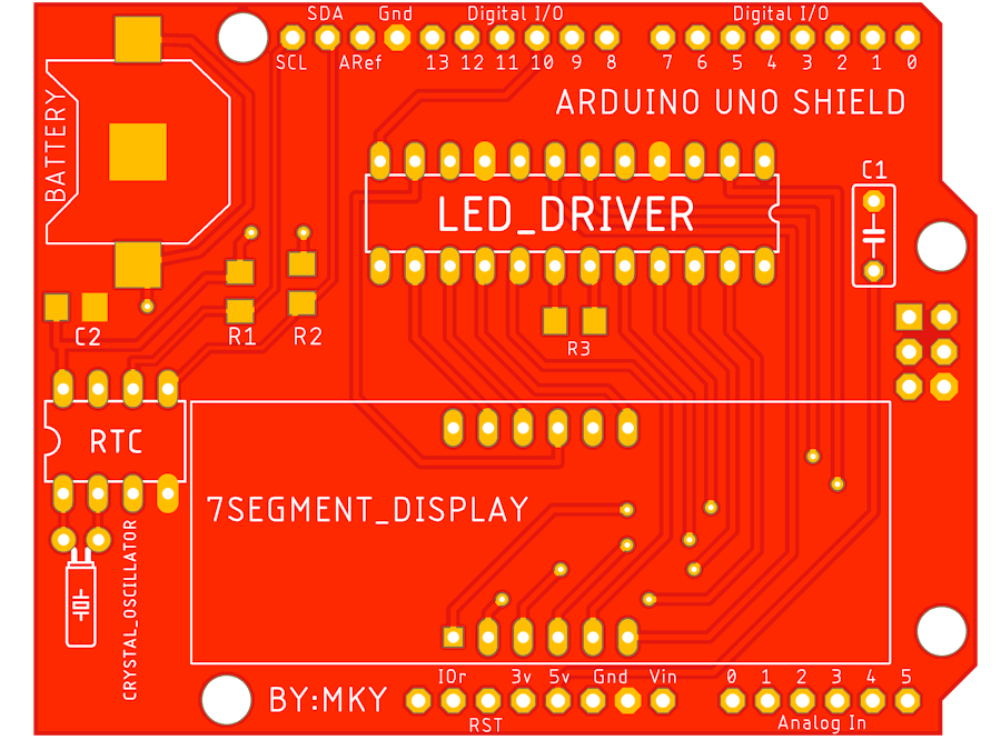
In this project, I have made a 4-Bit 7 segment display Arduino UNO shield using MAX 7219 IC. It is also compatible with Arduino Mega. I have made this design using Autodesk Eagle PCB Design software used worldwide by professionals.
First I make the schematic in the schematic editor, here I have used the bus tool to make the connection so our schematic looks clean and easy to read.
After completing the schematic run the ERC(Electrical rule check) and if there are any errors then resolve them. after that set the net classes according to your convenience or keep them as same as mine.
Now move to the board layout editor window and start placing your components on the board. Make sure to place the crystal oscillator as close to the RTC and apply a separate polygon for the oscillator.
Now route all the wires and finish routing after that apply polygon to both sides you can use ULP for that. after all this, your board will look like this
Now click on the Ratsnest tool and let the magic begins
After that run DRC(Design rule check) and look out for the errors and eliminate them. After your design is ready you can view it by clicking it on the manufacturing tab
You can change the color of the solder mask if you want by going into the configure option.
Now you can generate your Gerber files and order them from any PCB manufacturer. the final Board after attaching the component will look like this :
Connect it with Arduino and run the program to test the board. I will provide the schematic and board layout in the attachment below for reference.


_3u05Tpwasz.png?auto=compress%2Cformat&w=40&h=40&fit=fillmax&bg=fff&dpr=2)
Comments