


Hardware components | ||||||
 |
| × | 1 | |||
 |
| × | 3 | |||
 |
| × | 1 | |||
 |
| × | 1 | |||
| × | 1 | ||||
| × | 1 | ||||
| × | 1 | ||||
 |
| × | 1 | |||
| × | 1 | ||||
| × | 1 | ||||
 |
| × | 1 | |||
| × | 1 | ||||
Software apps and online services | ||||||
 |
| |||||
| ||||||
| ||||||
| ||||||
Hand tools and fabrication machines | ||||||
 |
| |||||
 |
| |||||
| ||||||
This is a smart car, able to follow a black path thanks to three line tracking sensors. Using a ultrasonic sensor it notices obstacles presence along its way and stops motors if this condition is true.
We built it to solve one of our own problems, moving indipendently objects. Studying carefully the possible solutions we opted for this one, effective and not too hard.
Here some images and videos to show its functioning.
On the back of the car there is a servo motor but we didn't use it.
To make this project we used an Elegoo kit bought online, its link has been added to the bill of materials, but is possible to build the device without purchasing it because part's drawings and all the components have been entered here.
The product is available at the following link:
https://www.elegoo.com/product/arduinocarv3-0/
1. Design and drawing phaseMost of the components were already made, but they have been drawn anyway, so it is possible to reproduce the project without buying the online kit. One part, not present but useful to implement the system, has been printed using a 3D printer, this object is a loading platform that allowed us to transport small goods and materials. All the drawings have been reported at the bottom of this paragraph.
The wheels have not been drawn. You can search them on Thingiverse: https://www.thingiverse.com/
- ElegooUNO R3 (x1)
- DC motor (x4): DC (Direct Current) motor is any type of rotary electrical machine that adapts this type of energy into mechanical energy. It is the most common type of motor and normally have just two leads, one positive and one negative; if you connect them directly to a battery, the motor will rotate, if you switch the leads, the motor will rotate in the opposite direction.
- L298N motor driver (x1): it is a H-Bridge motor driver which allows speed and direction control of DC motors. The module can drive DC motors that have voltages between 5 and 35V, with a peak current up to 2A. Using it we can change the direction of the current flow and consequentely the rotation direction of the motor. So if we combine the PWM and the H-Bridge, we can have a complete control over the DC motor. There are many DC motor drivers that have these features and the L298N is one of them. For more details consult the following links:
https://lastminuteengineers.com/l298n-dc-stepper-driver-arduino-tutorial/
- Line tracking sensor module KY-033 (x3): this module uses an IR transmitter and receiver that will detect how reflective the surface is in front of the module. It has a potentiometer to adjust the sensitivity of the module so it can detect if the surface is black or white.
- Ultrasonic sensor module HC-SR04 (x1): it emits an ultrasound at 40000 Hz which travels through the air and if there is an object or obstacle on its path it will come back to the module. Considering the travel time and the speed of the sound you can calculate the distance. Follow the link:
https://howtomechatronics.com/tutorials/arduino/ultrasonic-sensor-hc-sr04/
- Servo motor(x1): there are many types of servo motors and their main feature is the ability to precisely control the position of their shaft. A servo motor is a closed-loop system that uses position feedback to control its motion and final position. The actual position captured by these devices is fed back to the error detector where it is compared to the target position. Then according to the error the controller corrects the actual position of the motor to match with the target position. Useful link:
- Expansion board – Arduino sensor shield v5.0 (x1): the Arduino sensor shield allows you to connect various modules (like sensors, servos, relays, buttons, potentiometers etc.) to your Arduino Uno. Each pin has a corresponding VCC and GND pin to easily wire a module and supply power to it.
- Battery holder (x1)
- Battery – BRC 186504200mAh 3.7V li-ion (x2)
- DC connector-adapter(x1)
- Loading platform (x1)
- Connection wires
- Car frame (x2)
- Wheels (x4)
- Bolts
The means of transport that has been built can follow a black path, using three line tracking sensors put under theframe in front of the car; this is true only if the ultrasonic sensor, connected to a servomotor that describes an angle of 60°, reads a distance higherthan 20 cm. In this case there can be four different situations:
1. all the sensors are reading white colorso the car had lost the line, for this reason the motors are stopped, movingcould be dangerous for the people in the surrounding area;
2. all the sensors are reading black colorso the system is completely on the line, this appens for example when there isa stop indication and, also in this case, “Transporter” does not move;
3. left sensor/central sensor (both or onlythe first one) on the black line, the path’s state is changed, precisely itturns left, so also the car has to turn left to continue to follow the route;
4. right sensor/central sensor (both oronly the first one) on the black line, the path turns right and for this reasonalso “Transporter” has to turn right, in this way it is again in the correctposition.
Assuming these conditions acombinations’ table has been drawn up to know how the system built worked. Having:
- LS = line tracking sensor on the left;
- CS = line tracking sensor in the middle;
- RS = line tracking sensor on the right;
- END = ON/OFF right DC motors;
- ENS = ON/OFF left DC motors;
- IN1 = allows right DC motors to gobackwards;
- IN2 = allows right DC motors to goforwards;
- IN3 = allows left DC motors to goforwards;
- IN4 = allows left DC motors to gobackwards.
It is important to say that black coloris, for the sensors, HIGH or 1 while white color is for them LOW or 0.
Combinations table:
System’sfunctioning during the different states ():
- State 1 = all the DC motors are OFF (stop)
- State 2 = right DC motors go backward while left DC motors go forward (turn right)
- State 3 = right and left DC motors go forward (go forward)
- State 4 = right DC motors go backward while left DC motors go forward (turn right)
- State 5 = right DC motors go forward while left DC motors go backward (turn left)
- State 6 = all the DC motors are OFF (stop)
- State 7 = right DC motors go forward while left DC motors go backward (turn left)
- State 8 = all the DC motors are OFF (stop)
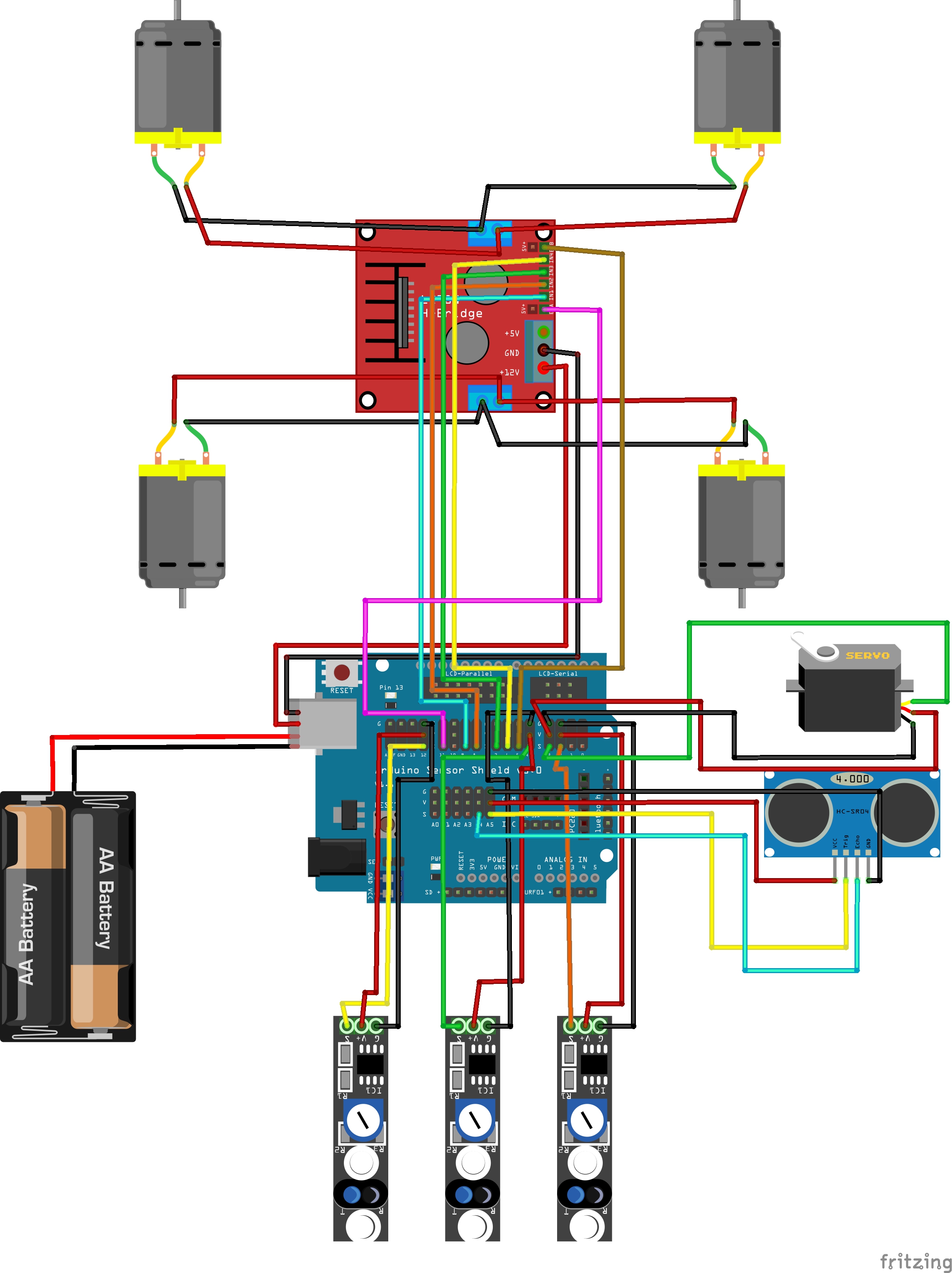
Now "Transporter" has been assembled, using the various bolts given. Initially the DC motors and theirrelated motor driver (L298N) have been screwed on the lower frame and the linetracking sensors have been connected under this part of the structure (precisely one on the left, the second in the middle and the last one on theright). Then the wheels have been sat to the motors, in this way they canrotate, and the higher frame has been screwed to the other one, using specificspacers. Subsequentely, on the upper part of the car, the Elegoo board, theexpansion board, the battery holder and the ultrasonic sensor, connected to aservomoto (positioned in a structure’s hole), have been assembled. Finally allthe parts assembled have been controlled to be sure that everything was working well.
The power supply is given by twobatteries (both of 3.7 V and 4200 mAh), inserted in a battery holder connectedto the Elegoo board using a DC adapter, and on the microcontroller has beenplaced an expansion board, that allowed us to have more pin and not to use abreadboard. After this assembly all the electrical connections have been donefollowing the scheme below.
In the scheme below has been omittedthe DC adapter, there was not in the Fritzing’s list and we did not find it on the web.
First listing elaboration
#include<NewPing.h>
#include<Servo.h>
int in1 =9;
int in2 =8;
int in3 =7;
int in4 =6;
int EnD =11;
int EnS =5;
int LS =12;
int CS =4;
int RS =2;
intvelNor = 70;
intvelRot = 140;
int pos1= 120;
int pos2= 60;
#defineTRIGGER_PIN A5
#defineECHO_PIN A4
#defineMAX_DISTANCE 200
ServoSMA;
NewPingsonar(TRIGGER_PIN, ECHO_PIN, MAX_DISTANCE);
voidsetup() {
pinMode(in1, OUTPUT);
pinMode(in2, OUTPUT);
pinMode(in3, OUTPUT);
pinMode(in4, OUTPUT);
pinMode(EnD, OUTPUT);
pinMode(EnS, OUTPUT);
pinMode(LS, INPUT);
pinMode(CS, INPUT);
pinMode(RS, INPUT);
SMA.attach(3);
SMA.write(pos1);
}
voidloop() {
SMA.write(pos1);
delay(150);
SMA.write(pos2);
delay(150);
do {
if (digitalRead(LS) == HIGH &&digitalRead(CS) == HIGH && digitalRead(RS) == LOW || digitalRead(LS) ==HIGH && digitalRead(CS) == LOW && digitalRead(RS) == LOW) {
analogWrite(EnD, velRot);
analogWrite(EnS, velRot);
digitalWrite(in1, LOW);
digitalWrite(in2, HIGH);
 digitalWrite(in3, LOW);
digitalWrite(in4, HIGH);
delay(100);
}
if (digitalRead(LS) == LOW &&digitalRead(CS) == HIGH && digitalRead(RS) == HIGH || digitalRead(LS)== LOW && digitalRead(CS) == LOW && digitalRead(RS) == HIGH) {
analogWrite(EnD, velRot);
analogWrite(EnS, velRot);
digitalWrite(in1, HIGH);
digitalWrite(in2, LOW);
digitalWrite(in3, HIGH);
digitalWrite(in4, LOW);
delay(100);
}
if (digitalRead(LS) == LOW &&digitalRead(CS) == HIGH && digitalRead(RS) == LOW) {
analogWrite(EnD, velNor);
analogWrite(EnS, velNor);
digitalWrite(in1, LOW);
digitalWrite(in2, HIGH);
digitalWrite(in3, HIGH);
digitalWrite(in4, LOW);
delay(100);
}
else {
digitalWrite(EnD, LOW);
digitalWrite(EnS, LOW);
delay(100);
}
} while (sonar.ping_cm() < 20);
}
This is the first listing that has been written, it contained a lot of if conditions and was not so efficient, for this reason it has been simplified and improvedusing Karnaugh’s maps.
The process has been entered below.
Combinationstable and Karnaugh’s maps
IN1 = RS * !LS
IN2 = !RS * CS + !RS * LS
IN2 = !RS * (CS + LS)
IN3 = RS * !LS + !LS * CS
IN3 = !LS * (CS + RS)
IN4 = !RS * LS
VelNor = !LS * CS * !RS
VelRot = RS * !LS + !RS * LS
Now the previous listing has been semplified using the results of the Karnaugh’s maps.
Completed listing
#include<NewPing.h>
#include<Servo.h>
intin1 = 9;
intin2 = 8;
intin3 = 7;
intin4 = 6;
intEnD = 11;
intEnS = 5;
int LS= 12;
int CS= 4;
int RS= 2;
intvelNor = 70;
int velRot= 110;
intperiod1 = 50;
intperiod2 = 120;
intpos1 = 120;
intpos2 = 60;
#defineTRIGGER_PIN A5
#defineECHO_PIN A4
#defineMAX_DISTANCE 200
NewPingsonar(TRIGGER_PIN, ECHO_PIN, MAX_DISTANCE);
ServoSMA;
voidsetup() {
pinMode(in1, OUTPUT);
pinMode(in2, OUTPUT);
pinMode(in3, OUTPUT);
pinMode(in4, OUTPUT);
pinMode(EnD, OUTPUT);
pinMode(EnS, OUTPUT);
pinMode(LS, INPUT);
pinMode(CS, INPUT);
pinMode(RS, INPUT);
SMA.attach(3);
SMA.write(pos1);
}
voidloop() {
while (sonar.ping_cm() < 20) {
SMA.write(pos1);
delay(period2);
SMA.write(pos2);
delay(period2);
digitalWrite(EnD, LOW);
digitalWrite(EnS, LOW);
delay(period1);
}
SMA.write(pos1);
delay(period2);
SMA.write(pos2);
delay(period2);
if (digitalRead(LS) == LOW &&digitalRead(CS) == HIGH && digitalRead(RS) == LOW) {
analogWrite(EnD, velNor);
analogWrite(EnS, velNor);
delay(period1);
}
else if (digitalRead(RS) == HIGH &&digitalRead(LS) == LOW || digitalRead(RS) == LOW && digitalRead(LS) ==HIGH) {
analogWrite(EnD, velRot);
analogWrite(EnS, velRot);
delay(period1);
}
digitalWrite(in1, digitalRead(LS) && digitalRead(RS));
digitalWrite(in2, digitalRead(RS) && (digitalRead(LS)
digitalWrite(in3, digitalRead(LS) && (digitalRead(RS)
digitalWrite(in4, digitalRead(LS) && digitalRead(RS));
delay(period1);
}
Flowchart
Finally Transporter prototype has been subjected to a final test, a circular path has been drawn using a black scotch tape and then thecheck started. As desired it followed the route and putting an obstacle on its way it stopped immediately. During this phase a movie has been recorded to prove device’s properly functioning.
We have done a line follower car, able to notice obstacles presence and to transport light objects.
Thanks to all the readers who will report any mistakes made or possible improvements.


_3u05Tpwasz.png?auto=compress%2Cformat&w=40&h=40&fit=fillmax&bg=fff&dpr=2)
Comments