


// This sketch is written by MBcreates (www.YouTube.com/MBcreates)
// this sketch is in the public domain and free to use in any way you see fit
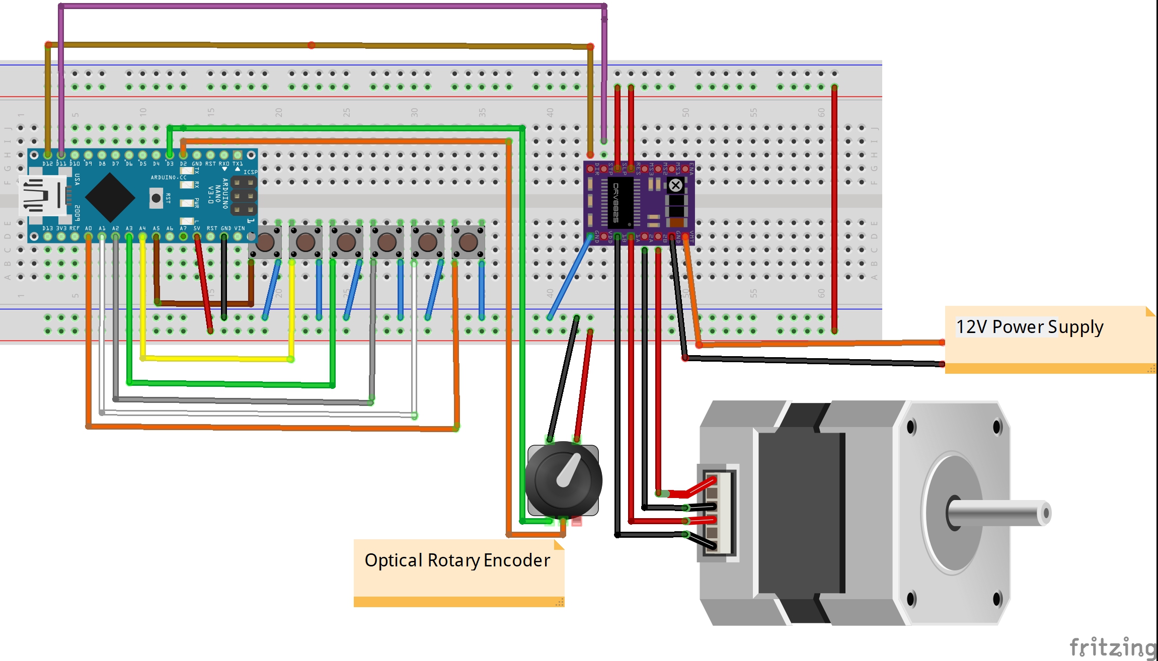
#define DIR 12 // DRV8825 DIR pin is connected to Arduino pin 12
#define STEP 11 // DRV8825 STEP pin is connected to Arduino pin 11
#define P1 14 // push button 1 is connected to Arduino pin A0
#define P2 15 // push button 2 is connected to Arduino pin A1
#define P3 16 // push button 3 is connected to Arduino pin A2
#define P4 17 // push button 4 is connected to Arduino pin A3
#define P5 18 // push button 5 is connected to Arduino pin A4
#define P6 19 // push button 6 is connected to Arduino pin A5
int DELAY = 1500; // delay between steps in microsenconds
int DISTANCE = 0 ; // Counter for steps
boolean GO = false; // stepper ON or OFF
int DEST = 0; // variable to store selected DESTINATION
int SOURCE =0; // variable to store current POSITION
int DIFF = 0; // variable to store the diffrence between POSISTION and DESTINATION
int DIFFplus=0; // variable to store a value to check what the shortest direction to DESTINATION is
int DIFFmin=0; // variable to store a value to check what the shortest direction to DESTINATION is
void setup() {
pinMode(DIR,OUTPUT); // pin 12 is set to OUTPUT
pinMode(STEP,OUTPUT); // pin 11 is set to OUTPUT
pinMode(P1,INPUT_PULLUP); // Arduino pin A0 is set to INPUT_PULLUP
pinMode(P2,INPUT_PULLUP); // Arduino pin A1 is set to INPUT_PULLUP
pinMode(P3,INPUT_PULLUP); // Arduino pin A2 is set to INPUT_PULLUP
pinMode(P4,INPUT_PULLUP); // Arduino pin A3 is set to INPUT_PULLUP
pinMode(P5,INPUT_PULLUP); // Arduino pin A4 is set to INPUT_PULLUP
pinMode(P6,INPUT_PULLUP); // Arduino pin A5 is set to INPUT_PULLUP
}
void loop() {
/////////////////////////////// Selecting DESTINTATION by PUSH BUTTON
/*
The test setup in the video uses a 1.8 degree stepper motor. The Stepper driver is set to full step. This makes for 200 steps for a full rotation.
Six diffrent posistion make for 33,333 steps between posistions. I used vife times 33 steps and one time 35 steps to avoid decimal values
*/
if(!digitalRead(P1)) // when button 1 is pushed, DESTINATION is set to 0
{
DEST=0;
}
if(!digitalRead(P2)) // when button 2 is pushed, DESTINATION is set to 33
{
DEST=33;
}
if(!digitalRead(P3)) // when button 3 is pushed, DESTINATION is set to 66
{
DEST=66;
}
if(!digitalRead(P4)) // when button 4 is pushed, DESTINATION is set to 99
{
DEST=99;
}
if(!digitalRead(P5)) // when button 5 is pushed, DESTINATION is set to 132
{
DEST=132;
}
if(!digitalRead(P6)) // when button 6 is pushed, DESTINATION is set to 165
{
DEST=165;
}
DIFF=100-abs(abs(SOURCE-DEST)-100); // the diffrence between SOURCE and DESTINATION is callculated in a way the value is always positive
// the two calculations below check the fastest way around a circle
// learn more here: https://stackoverflow.com/questions/7428718/algorithm-or-formula-for-the-shortest-direction-of-travel-between-two-degrees-on
DIFFplus=100-abs(abs((SOURCE+1)-DEST)-100); // the diffrence between SOURCE+1 and DESTINATION is callculated in a way the value is always positive
DIFFmin=100-abs(abs((SOURCE-1)-DEST)-100); // the diffrence between SOURCE-1 and DESTINATION is callculated in a way the value is always positive
if(DIFFplus>=DIFFmin) // rotaion dirrection is set
{
digitalWrite(DIR,LOW);
}
else
{
digitalWrite(DIR,HIGH);
}
if(DEST!=SOURCE){ // if there is a diffrence between DEST and SOURCE, GO is set to true
GO=true;
while (GO) // while there is a diffrence between DEST and SOURCE the motor steps
{
digitalWrite(STEP,HIGH);
delayMicroseconds(DELAY);
digitalWrite(STEP,LOW);
delayMicroseconds(DELAY);
DISTANCE++; // DISTANCE increases with 1 after every step
if (DISTANCE==DIFF) // when the DISTANCE is equal to DIFF, the
{
GO=false; // GO is set to false
SOURCE=DEST; // SOURCE is set to DEST (now both values are the same)
DISTANCE=0; // the DISTANCE counter is reset to zero
}
}
}
}
// This sketch is written by  MBcreates (www.YouTube.com/MBcreates)
// this sketch is in the public domain and free to use in any way you see fit


/*
 the Rotary Encoder code part of this sketch was found on:

 https://github.com/jumejume1/Arduino/blob/master/ROTARY_ENCODER/ROTARY_ENCODER.ino

 thanks jumejume1 for sharing.
*/


#define DIR   12     // DRV8825 DIR pin is connected to Arduino pin 12
#define STEP  11     // DRV8825 STEP pin is connected to Arduino pin 11

#define P1    14    // push button 1 is connected to Arduino pin A0
#define P2    15    // push button 2 is connected to Arduino pin A1
#define P3    16    // push button 3 is connected to Arduino pin A2
#define P4    17    // push button 4 is connected to Arduino pin A3
#define P5    18    // push button 5 is connected to Arduino pin A4
#define P6    19    // push button 6 is connected to Arduino pin A5

int DELAY = 380;   // delay between steps in microsenconds
int DISTANCE=0;   // Counter for steps

int DEST = 0;       // variable to store selected DESTINATION
int SOURCE =0;      // variable to store current POSITION
int DIFF = 0;       // variable to store the diffrence between POSISTION and DESTINATION
int DIFFplus=0;     // variable to store a value to check what the shortest direction to DESTINATION is
int DIFFmin=0;      // variable to store a value to check what the shortest direction to DESTINATION is

int encoderA;     // variable to store the encoder value before a movement
int encoderB;     // variable to store the encoder value after a movement
int encoderD;     // the diffrence between encoderA and encoderB
int counter = 0;  //variable to store the encoder value

boolean GO = false;   // stepper ON or OFF
boolean PRINT=false;    // variable used to print the encoderD value

void setup() {

 Serial.begin(9600);   // start serial montior

 pinMode(DIR,OUTPUT);       // pin 12 is set to OUTPUT
 pinMode(STEP,OUTPUT);      // pin 11 is set to OUTPUT

 pinMode(P1,INPUT_PULLUP);  // Arduino pin A0 is set to INPUT_PULLUP
 pinMode(P2,INPUT_PULLUP);  // Arduino pin A1 is set to INPUT_PULLUP
 pinMode(P3,INPUT_PULLUP);  // Arduino pin A2 is set to INPUT_PULLUP
 pinMode(P4,INPUT_PULLUP);  // Arduino pin A3 is set to INPUT_PULLUP
 pinMode(P5,INPUT_PULLUP);  // Arduino pin A4 is set to INPUT_PULLUP
 pinMode(P6,INPUT_PULLUP);  // Arduino pin A5 is set to INPUT_PULLUP

 // this rotary encoder sketch uses the interupt pins on the arduino. note every pin can be used for this purpose
 // learn more here: https://www.arduino.cc/reference/en/language/functions/external-interrupts/attachinterrupt/

 pinMode(2, INPUT_PULLUP); // internal pullup input pin 2
 pinMode(3, INPUT_PULLUP); // internal pullup input pin 3

 //Setting up interrupt
 //A rising pulse from encodenren activated ai0(). AttachInterrupt 0 is DigitalPin nr 2 on moust Arduino.
 attachInterrupt(0, ai0, RISING);

 //B rising pulse from encodenren activated ai1(). AttachInterrupt 1 is DigitalPin nr 3 on moust Arduino.
 attachInterrupt(1, ai1, RISING);

}

void loop() {

  //Serial.println(counter);

/////////////////////////////// Selecting DESTINTATION by PUSH BUTTON
/*
The test setup in the video uses a 1.8 degree stepper motor. The Stepper driver is set to full step. This makes for 200 steps for a full rotation.
Six diffrent posistion make for 33,333 steps between posistions. I used vife times 33 steps and one time 35 steps to avoid decimal values

*/

if(!digitalRead(P1))      // when button 1 is pushed, DESTINATION is set to 0
  {
    DEST=0;
  }
if(!digitalRead(P2))      // when button 2 is pushed, DESTINATION is set to 33
  {
    DEST=33;
  }
if(!digitalRead(P3))      // when button 3 is pushed, DESTINATION is set to 66
  {
    DEST=66;
  }
if(!digitalRead(P4))      // when button 4 is pushed, DESTINATION is set to 99
  {
    DEST=99;
  }
if(!digitalRead(P5))      // when button 5 is pushed, DESTINATION is set to 132
  {
    DEST=132;
  }
if(!digitalRead(P6))      // when button 6 is pushed, DESTINATION is set to 165
  {
    DEST=165;
  }


DIFF=100-abs(abs(SOURCE-DEST)-100);             // the diffrence between SOURCE and DESTINATION is callculated in a way the value is always positive

//  the two calculations below check the fastest way around a circle
//   learn more here: https://stackoverflow.com/questions/7428718/algorithm-or-formula-for-the-shortest-direction-of-travel-between-two-degrees-on

DIFFplus=100-abs(abs((SOURCE+1)-DEST)-100);     // the diffrence between SOURCE+1 and DESTINATION is callculated in a way the value is always positive
DIFFmin=100-abs(abs((SOURCE-1)-DEST)-100);      // the diffrence between SOURCE-1 and DESTINATION is callculated in a way the value is always positive


if(DIFFplus>=DIFFmin)                 // rotaion dirrection is set
{
  digitalWrite(DIR,LOW);
 }

else
  {
  digitalWrite(DIR,HIGH);
  }


if(DEST!=SOURCE)
  {              // if there is a diffrence between DEST and SOURCE, GO is set to true
  GO=true;
  encoderA = counter;          // the encoder position before the movement start is stored encoder A
  }

  while (GO)                  // while there is a diffrence between DEST and SOURCE the motor steps
 {
  digitalWrite(STEP,HIGH);
  delayMicroseconds(DELAY);
  digitalWrite(STEP,LOW);
  delayMicroseconds(DELAY);
  DISTANCE++;                 // DISTANCE increases with 1 after every step


 if (DISTANCE==DIFF)        // when the DISTANCE is equal to DIFF, the
  {
  GO=false;                 // GO is set to false
  SOURCE=DEST;              // SOURCE is set to DEST (now both values are the same)
  DISTANCE=0;               // the DISTANCE counter is reset to zero
  PRINT=true;               // PRINT is set to true

  }
}

delay(50);              //wait until the setups is stoped completely
encoderB = counter;     // the encoder position is stored in encoderB

encoderD=32752+(1/2)-abs(abs(encoderA-encoderB)-32752+(1/2)); //  the diffrence between encoder A & B is calculated and stored in encoderD

/*

the optical rotary encoder used in this setup can go from 0 to 65504 (clockwise) or from 0 to -65504 (counter clockwise).
the forumula above calculates always a postive value and also ensures that when the max encoder value is reached the encoderD value is still correct

this encoder setup gives a value of 1200 for a full rotation of the stepper motor

*/

if(PRINT)                         // the encoderD value is printed one time after each movement
{
  Serial.println(encoderD);
  PRINT=false;
}


}   // end of porgram

 void ai0() {
  // ai0 is activated if DigitalPin nr 2 is going from LOW to HIGH
  // Check pin 3 to determine the direction
  if(digitalRead(3)==LOW) {
  counter++;
  }else{
  counter--;
  }
  }

  void ai1() {
  // ai0 is activated if DigitalPin nr 3 is going from LOW to HIGH
  // Check with pin 2 to determine the direction
  if(digitalRead(2)==LOW) {
  counter--;
  }else{
  counter++;
  }
  }
// This sketch is written by  MBcreates (www.YouTube.com/MBcreates)
// this sketch is in the public domain and free to use in any way you see fit


/*
 the Rotary Encoder code part of this sketch was found on:

 https://github.com/jumejume1/Arduino/blob/master/ROTARY_ENCODER/ROTARY_ENCODER.ino

 thanks jumejume1 for sharing.
*/


#define DIR   12     // DRV8825 DIR pin is connected to Arduino pin 12
#define STEP  11     // DRV8825 STEP pin is connected to Arduino pin 11

#define P1    14    // push button 1 is connected to Arduino pin A0
#define P2    15    // push button 2 is connected to Arduino pin A1
#define P3    16    // push button 3 is connected to Arduino pin A2
#define P4    17    // push button 4 is connected to Arduino pin A3
#define P5    18    // push button 5 is connected to Arduino pin A4
#define P6    19    // push button 6 is connected to Arduino pin A5

int DELAY = 400;         // delay between steps in microsenconds(the initial movement)
int DELAY_SLOW = 1200;   // delay between steps in microsenconds(the second reverse movement)


int BRAKE = 50;          // delay between end of rotation and encoderB measurment in miliseconds
int OFFSET= 20;             //  value to set the number of steps the stepper should overshoot its target

int encoderA;     //encoder before moving
int encoderB;     //encoder after moving
int encoderD;     //econder Delta


volatile unsigned int temp = 0;  //This variable will increase or decrease depending on the rotation of encoder
int counter = 0;
int DISTANCE=0;

int I_OVERSHOT=0;
int CORRECTED=0;

int CORRECT=0;

int LOR=0;

boolean GO = false;
boolean DIR_REV = false;

int DEST = 0;
int SOURCE =0;
int DIFF = 0;
int DIFFplus=0;
int DIFFmin=0;
int CHECK=0;
int BOUNCE=100;

boolean C1=false;
boolean C2=false;
boolean C3=false;
boolean C4=false;
boolean REVERSE=false;


void setup() {

  Serial.begin(9600);

 pinMode(2, INPUT_PULLUP); // internal pullup input pin 2

  pinMode(3, INPUT_PULLUP); // internal pullup input pin 3
//Setting up interrupt
  //A rising pulse from encodenren activated ai0(). AttachInterrupt 0 is DigitalPin nr 2 on moust Arduino.
  attachInterrupt(0, ai0, RISING);

  //B rising pulse from encodenren activated ai1(). AttachInterrupt 1 is DigitalPin nr 3 on moust Arduino.
  attachInterrupt(1, ai1, RISING);


 pinMode(DIR,OUTPUT);
 pinMode(STEP,OUTPUT);

 pinMode(P1,INPUT_PULLUP);
 pinMode(P2,INPUT_PULLUP);
 pinMode(P3,INPUT_PULLUP);
 pinMode(P4,INPUT_PULLUP);
 pinMode(P5,INPUT_PULLUP);
 pinMode(P6,INPUT_PULLUP);


}

void loop() {

    //Serial.println(counter);

if(!digitalRead(P1))

  {
    delay(BOUNCE);
    DEST=0;
  }

if(!digitalRead(P2))

  {
    delay(BOUNCE);
    DEST=200;
  }

if(!digitalRead(P3))

  {
    delay(BOUNCE);
    DEST=400;
  }

if(!digitalRead(P4))

  {
    delay(BOUNCE);
    DEST=600;
  }

if(!digitalRead(P5))

  {
    delay(BOUNCE);
    DEST=800;
  }

if(!digitalRead(P6))

  {
    delay(BOUNCE);
    DEST=1000;
  }


DIFF=600-abs(abs(SOURCE-DEST)-600);
DIFFplus=600-abs(abs((SOURCE+1)-DEST)-600);
DIFFmin=600-abs(abs((SOURCE-1)-DEST)-600);


 /////////////////////// Direction

if(DIFFplus>DIFFmin)
{
  digitalWrite(DIR,LOW);     //counter CLOCK wise
 }

if(DIFFplus<=DIFFmin)
  {
  digitalWrite(DIR,HIGH);  //CLOCK wise
  //Serial.println("X");
  }

//

//////////////////////////////Movement


if(DEST!=SOURCE){   // diffrence between Source and Destination is tested
  GO=true;
  encoderA = counter;          // the position before the movement start is stored encoder A

       // Serial.print("SOURCE");
 // Serial.println(SOURCE);

        //  Serial.print("DEST");
 // Serial.println(DEST);


     // Serial.print("DIFF");
 // Serial.println(DIFF);

   //   Serial.print("DIFFplus");
// Serial.println(DIFFplus);

     // Serial.print("DIFFmin");
  //Serial.println(DIFFmin);


 }

  while (GO)
 {

  digitalWrite(STEP,HIGH);
  delayMicroseconds(DELAY);
  digitalWrite(STEP,LOW);
  delayMicroseconds(DELAY);
   encoderB = counter;
   encoderD=32752+(1/2)-abs(abs(encoderA-encoderB)-32752+(1/2)); //  the diffrence between encoder A & B is calculated and stored in encoderD


 if (encoderD > (DIFF+OFFSET))
  {
  GO=false;
  //SOURCE=DEST;                        ///// remove this line
  C1=true;

  }
}

if(C1)
{

  delay(BRAKE);         // make sure the setup stoped completely
  encoderB = counter;
  encoderD=32752+(1/2)-abs(abs(encoderA-encoderB)-32752+(1/2)); //  update encoderD

   // Serial.print("encoderD   ");
  //Serial.println(encoderD);


 I_OVERSHOT=encoderD-DIFF; // POS is set to the value the stepper is stoped
  C1=false;
  C2=true;

   // Serial.print("I_OVERSHOT   ");
 // Serial.println(I_OVERSHOT);

}


while(C2)

{

   if(DIFFplus>DIFFmin)
  {
  digitalWrite(DIR,HIGH);   //clock
  DIR_REV=false;
   }

 if(DIFFplus<=DIFFmin)
  {
  digitalWrite(DIR,LOW);    //counter
  DIR_REV=true;
  }

  C2=false;
  REVERSE=true;
  encoderA = counter;          // the position before the movement start is stored encoder A
   // Serial.print("LOR");
 // Serial.println(LOR);


}


while (REVERSE)
 {
 // Serial.println("Y");
  digitalWrite(STEP,HIGH);
  delayMicroseconds(DELAY_SLOW);
  digitalWrite(STEP,LOW);
  delayMicroseconds(DELAY_SLOW);

   encoderB = counter;
   encoderD=32752+(1/2)-abs(abs(encoderA-encoderB)-32752+(1/2)); //  the diffrence between encoder A & B is calculated and stored in encoderD

if(encoderD>=I_OVERSHOT)      //
{
  REVERSE=false;
  C3=true;

}
 }

if(C3)
{

delay(BRAKE); // make sure the setup stoped completely

   encoderB = counter;
   encoderD=32752+(1/2)-abs(abs(encoderA-encoderB)-32752+(1/2)); //  the diffrence between encoder A & B is calculated and stored in encoderD
   CORRECTED = encoderD;
C3=false;
C4=true;

   // Serial.print("CORRECTED   ");
 // Serial.println(CORRECTED);

}

while(C4)
{
  if(CORRECTED==I_OVERSHOT)    // the correction was spott. SOURCE can be set to DEST and no correction is needed
  {
    SOURCE=DEST;
  //   Serial.println("1");
  }


  if((CORRECTED < I_OVERSHOT)&& (DIR_REV))      // (1) clock high (2) counter low   // UNDERCORRECTED  xx
  {

        SOURCE = (DEST + (I_OVERSHOT-CORRECTED)) ;
        DEST=SOURCE;


     //    Serial.print("SOURCE   ");
    //  Serial.println(SOURCE);

   // Serial.print("DEST   ");
  //  Serial.println(DEST);


  // Serial.println("2");
 // Serial.println();
    }

/*  pos 0>>> pos 200
 *   pos 0>>> pos 210
 *
 *        pos205<<<pos 210    diffrence = CORRECTED

      new source = dest + corrected
...
1000>>>0
 *  I_over 1000>>>50
 *        30<<<50

      new source(previous dest + CORRECTED = 0+20 = 205


*/

    if((CORRECTED > I_OVERSHOT)&& (DIR_REV))      // (1) clock high (2) counter low   // overcorrect  xx
  {
            SOURCE = (DEST - (CORRECTED-I_OVERSHOT)) ;
        DEST=SOURCE;
                                                                        // note: DEST and SOURCE can become negative, fix that whith something

 //  Serial.print("SOURCE   ");
//  Serial.println(SOURCE);

 //  Serial.print("DEST   ");
 // Serial.println(DEST);

  //    Serial.println("3");
 // Serial.println();

  }

  if(SOURCE<0)
  {
    DEST = 1200+SOURCE;
    SOURCE=DEST;
    //Serial.println("VALUE IN BOX 3 IS CORRECTED   ");
   }


   if((CORRECTED < I_OVERSHOT)&& (!DIR_REV))      //(1)counter high (2) CLOCK low //UNDERCORRECTED
  {

  SOURCE= (DEST-(I_OVERSHOT-CORRECTED)) ;
  DEST=SOURCE;


    // Serial.print("SOURCE   ");
 // Serial.println(SOURCE);

  //Serial.print("DEST   ");
  //Serial.println(DEST);
   //   Serial.println("4");
 // Serial.println();


  }

    if((CORRECTED > I_OVERSHOT)&& (!DIR_REV))       //(1)counter high (2) CLOCK low//OVERCORRECTED
  {

  SOURCE= (DEST-(I_OVERSHOT-CORRECTED)) ;
  DEST=SOURCE;

 //  Serial.print("SOURCE   ");
  //Serial.println(SOURCE);

  // Serial.print("DEST   ");
  //Serial.println(DEST);
   //   Serial.println("5");
 // Serial.println();

  }
  C4=false;
}


}   // end of porgram


/*


 example: initial is clockwise

 Source = 0
 DEST = 200
 Diff = 200
 I_OVERSHOT = 35   (possitie 235)
REVERSE >

encoderD  40

R_overshot = (encoderD - I_OVERSHOT) = 5   (positie 195)

SOURCE = DEST + (-1* R_overshot) = 195

SOURCE=600-abs(abs(DEST-I_OVERSHOT)-600);


.....

Source = 1000
 DEST = 0
 Diff = 200
 I_OVERSHOT = 35   (possitie 35)
REVERSE >

encoderD  40

R_overshot = (encoderD - I_OVERSHOT) = 5   (positie 1195)

SOURCE = DEST + (-1* R_overshot) = 195

        0


SOURCE=600-abs(abs(DEST-I_OVERSHOT)-600);


...............

example: initial is counter clockwise

 Source = 0
 DEST = 1000
 Diff = 200
 I_OVERSHOT = 35   (possitie 965)
REVERSE >

encoderD  40

R_overshot = (encoderD - I_OVERSHOT) = 5   (positie 1005)

SOURCE = DEST + R_overshot

........................................


*/


/*

    if(encoderD > OVERSHOT)
  {

  }


 // Serial.print("CORRECT");
//  Serial.println(CORRECT);


    SOURCE= (DEST +(CORRECT*LOR));
    DEST=SOURCE;
    C3=false;

 // Serial.print("SOURCE");
 // Serial.println(SOURCE);
  Serial.println();
}


*/


 void ai0() {
  // ai0 is activated if DigitalPin nr 2 is going from LOW to HIGH
  // Check pin 3 to determine the direction
  if(digitalRead(3)==LOW) {
  counter++;
  }else{
  counter--;
  }
  }

  void ai1() {
  // ai0 is activated if DigitalPin nr 3 is going from LOW to HIGH
  // Check with pin 2 to determine the direction
  if(digitalRead(2)==LOW) {
  counter--;
  }else{
  counter++;
  }
  }


  /*
  Serial.print("counter");
  Serial.println(counter);


    Serial.print("encoderA");
  Serial.println(encoderA);

    Serial.print("encoderB");
  Serial.println(encoderB);


  Serial.print("counter");
  Serial.println(counter);
  Serial.print("delta");
  Serial.println(encoderD);

  Serial.println("X");

*/


/*
  Serial.print("encoderA1");
  Serial.println(encoderA);

    Serial.print("encoderB1");
  Serial.println(encoderB);

    Serial.print("STOPPED");
  Serial.println(STOPPED);
  */

Comments