/* The board is Adafruit Feather 32U4 Basic Proto
Read Time & Date from PCF8523 RTC built in Feather Adalogger
PCF8523 RTC connected via I2C and Wire lib
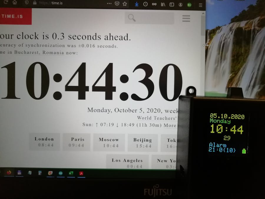
TFT (128x128)connected via SPI connector installed on Feather 32U4
A9 is connected by 1/2 voltage divider to BAT pin
Continous Run. Stop Feather Basic Proto & display by connecting En-pin to GND by an external switch.
v7: includes DST correction. Optimized value 20 for 0x0E for this RTC. Error < 7.5 s/MONTH!
v8: uses adjustClock to set the RTC from Serial Monitor.
Sketch uses 24450 bytes (85%) of program storage space. Maximum is 28672 bytes.
Global variables use 871 bytes of dynamic memory.
v9: Makes also monthly corrections of several seconds. Error < 0.5 s/MONTH!
Sketch uses 26074 bytes (90%) of program storage space. Maximum is 28672 bytes.
Global variables use 1053 bytes of dynamic memory.
v10: Minor corrections
Sketch uses 26068 bytes (90%) of program storage space. Maximum is 28672 bytes.
Global variables use 1053 bytes of dynamic memory.
*/
#include <Wire.h>
#include "RTClib.h" // Clock library
#include <SPI.h> //
#include <Adafruit_GFX.h> // Display Core graphics library
#include <Adafruit_ST7735.h> // Display Hardware-specific library
#define TFT_RST A5 // [9] but you can also connect this to the Arduino RESET PIN
#define TFT_CS 12 // Marked TCS on the 1.4" TFT
#define TFT_DC 11 // Marked D/C
#define CARD_CS 10 // Marked CARD_CS
#define Light 5 // Back-light display control (PWM pin)
#define BAT A9 // Battery voltage pin
#define REL 6 // Pin connected to the Relay/External LED
RTC_PCF8523 rtc;
#define _I2C_WRITE write
#define _I2C_READ read
char daysOfTheWeek[7][12] = {"Sunday ", "Monday ", "Tuesday ", "Wednesday", "Thursday ", "Friday ", "Saturday "};
// Use the hardware SPI pins
Adafruit_ST7735 tft = Adafruit_ST7735(TFT_CS, TFT_DC, TFT_RST);
float Vbat;
uint8_t dst, MM, DD, WD, hh, mm, ss;
uint16_t color, YY, setdate[3]={0};
uint16_t x0 = 0, y0 = 0; // Select display start position (x0,y0)
uint8_t oldsec = 0, newsec = 0, ontime = 25; // ontime = display on
int nrd, serr, corr, hcor = 0, corr3 = 0 ; //computed corrections per day, per 3h, to get the accurate time.
int corrM = 5; // Input= This particular RTC time error per Month! Even this is corrected.
bool adj = false, alarmon = false, view = false, visible = true;
unsigned long startMillis = 0, startscr = 0, tic; // seconds since RTC setup, timers
char buffer[24]; // Text buffer
byte val;
// ========================================================================================
// Set alarm implicit time (alarmh, ~m, ~s) and alarmlapse = relay-ON-duration(s):
int alarmh = -1, alarmm = -1, alarmlapse = 10; // -1 for hh and/or mm => "any" hh and/or mm
// =========================================================================================
byte bcdToDec(byte val){
return( (val/16*10) + (val%16) );
}
// ========================================================================================
byte decToBcd(byte val){
return( (val/10*16) + (val%10) );
}
// ========================================================================================
void adjustClock() {
// Serial Monitor must be open during Setup to change Date & Time. Else, no change in RTC settings.
// Serial Monitor input: "yyyy/mm/dd-hh:mm:ss"
// If all correct, input any char to exit, e.g. Enter in the input window
String data="";
if(Serial){
//Serial.println(">> Set RTC date, hour, minute, second : ");
Serial.println(">> Use Serial input: yyyy/mm/dd-hh:mm:ss , check & press any key when ok.");
while (data.length() < 1) { // If last data string is longer than 1 chars (e.g. Enter), exit!
if (Serial.available() > 0) { // Is a character available?
data = Serial.readString(); // Read the input as data string
}
if (data.length()>3){ // Proceed only with longer strings
uint16_t YYYY = data.substring(0, 4).toInt(); // read YYYY
uint8_t MM = data.substring(5, 7).toInt(); // read MM
uint8_t DD = data.substring(8, 10).toInt(); // ...
uint8_t hh = data.substring(11, 13).toInt();
uint8_t mm = data.substring(14, 16).toInt();
uint8_t ss = data.substring(17, 19).toInt();
rtc.adjust(DateTime(YYYY, MM, DD, hh, mm, ss)); // Set the RTC
data=""; // Clear the string
dst= DST(YYYY,MM,DD); // Determine DST at setup
setregisters(YYYY,MM,DD,dst); // Keep set day in RTC registers
}
gettime(true); // Read and show the RTC time on Serial monitor
delay(900); // Enough for one time read / s
}
Serial.println(F(">>Done: Date & time checked/reset!")); // user exiting.
// In case you want to set the Alarm ring time:
Serial.print("Existing RTC alarm = ");Serial.print(alarmh);Serial.print(":");Serial.println(alarmm);
Serial.println(">> Set RTC alarm, hour, minute, alarm_duration : ");
Serial.println(">> Use Serial input: hh:mm:alduration , check & press any key when ok.");
data=""; // Clear the string
while (data.length() < 1) { // If last data string is longer than 1 chars (e.g. Enter), exit!
if (Serial.available() > 0) { // Is a character available?
data = Serial.readString(); // Read the input as data string
}
if (data.length()>3){ // Proceed only with longer strings
alarmh = data.substring(0, 2).toInt(); // Alarm hour
alarmm = data.substring(3, 5).toInt(); // Alarm minute
alarmlapse = data.substring(6, 8).toInt(); // Alarm ring duration
//Serial.print(alarmh);Serial.print(":");Serial.print(alarmm);
//Serial.print("{");Serial.print(alarmlapse);Serial.println("}");
data=""; // Clear the string
}
}
Serial.println(F(">>Done: Alarm time set/reset!")); // user exiting Alarm setting!
int val=128 | decToBcd(alarmm); // convert alarmm to BCD and set it off
write_i2c_register(PCF8523_ADDRESS,0x0A,val); // store in 0A
val= 127 & decToBcd(alarmh); // convert alarmh to BCD and set it on
write_i2c_register(PCF8523_ADDRESS,0x0B,val); // store in 0B
} // end if Serial open
// Here the setup time should be stored in RTC Eprom memory!
}
// ========================================================================================
void setregisters(uint16_t YYYY, uint8_t MM, uint8_t DD, uint8_t dst){
// Depending on RTC, the setup date should be stored: YYYY / MM / DD & dst
// In PCF8523 there is not enough available memory for all:
// only dst,MM & YYYY (as offset, up to max 2027) are stored
int val=128 | ((dst<<4) + MM); // keep dst in bit 4 & MM (bits 3-0)
// Serial.println(val,BIN);
write_i2c_register(PCF8523_ADDRESS,0x0C,val); // dst & MM stored in 0C
val = 128 | (YYYY-2020) ; // Keep YYYY = 2020 + x<7
//Serial.println(val,BIN);
write_i2c_register(PCF8523_ADDRESS,0x0D,val); // MM < 7 stored in 0D
}
// ========================================================================================
void getsetupdate() {
// This is a RTC specific function, retrievig from RTC registers, the setup date.
// In PCF8523 there is available memory only for:
// dst, MM & YYYY (as offset to 2020, up to max 2027)
setdate[1] = (read_i2c_register(PCF8523_ADDRESS,0x0D) & 0X01) + 2020; // Read setdate[1] = YYYY
setdate[2] = read_i2c_register(PCF8523_ADDRESS,0x0C) & 0X0F; // Read MM
setdate[3] = (read_i2c_register(PCF8523_ADDRESS,0x0C) & 0X10) >> 4; // Read bit 4: DST(0/1)
// Read the Alarm data stored in registers:
alarmh= bcdToDec(read_i2c_register(PCF8523_ADDRESS,0x0B) & 127);
alarmm= bcdToDec(read_i2c_register(PCF8523_ADDRESS,0x0A) & 127);
}
//=========================================================================================================
int selfadjustime() {
/* Used to adjust shown time, for every 24h since RTC setup.
* Useful if no RTC adjust register is available, e.g. for DS1307.
* You determine the RTC correction in seconds per each passing day! Put this in corr24.
* Given: corr24 = +/- seconds to add/subtract to get the correct time per 24H.
* The setup time must be read from RTC non-volatile memory, as for DS1307.
* This value is RTC dependent and has to be termined for each case (a global variable).
* The temperature dependency of its accuracy is not accounted for, in the case of DS1307!
* This function is called every hour and if another 24h passed since setup, a corr24 is done.
*
* For other RTC-s, this is just to show setup date & DST at that time.
*/
getsetupdate(); // Read from RTC registers setup date: YYYY, MM, DST
Serial.print("The RTC was set: "); Serial.print(setdate[1]);Serial.print("/"); Serial.println(setdate[2]);
Serial.print("At Setup DST was: ");Serial.println(setdate[3]);
DateTime now = rtc.now(); // Read time form RTC
// Offset (s) cumulated over years & months:
int ser = -(now.month()-setdate[2] + (now.year() - setdate[1])*12 ) *corrM ;
return ser;
}
//=========================================================================================================
//void showTimeSpan( char* txt, const TimeSpan& ts) {
// // Extract the number of days since RTC set-up, for 24h correction
// uint16_t nrd = ts.days();
//}
//=========================================================================================================
uint8_t DST(uint16_t YYYY, uint8_t MM, uint8_t DD) {
//----------Daylight Saving Time (DST) in Europe -------------
// Compute for a given date the DST value = 0 or 1 hour.
uint8_t dst = 0; // For winter time
if (MM > 3 && MM < 10) // For summer months DST=1
dst = 1;
uint8_t ndays = 31 - ((5 * YYYY) / 4 + 4) % 7;
if (MM == 3 && DD >= ndays) // For some days in March DST=1
dst = 1;
ndays = 31 - ((5 * YYYY) / 4 + 1) % 7;
if (MM == 10 && DD < ndays) // For some days in October DST=1
dst = 1;
// Up to here: DST=1 for the correct calendar days.
return dst;
}
//=========================================================================================================
void gettime(bool show) {
// Read and adjust time form RTC. {show=1 : show time on LCD}
DateTime now = rtc.now(); // Read time form RTC
YY = now.year(); MM = now.month(); DD = now.day();
hh = now.hour(); mm = now.minute(); ss = now.second();
// If Serial Monitor is ON & show=1, then show the RTC time =============================================
if (Serial && show) {
// Show RTC time on Serial monitor, LCD or another display, as selected below:
Serial.print(YY); Serial.print("/"); Serial.print(MM); Serial.print("/"); Serial.print(DD);Serial.print(" ");
Serial.print(hh); Serial.print(":"); Serial.print(mm); Serial.print(":"); Serial.println(ss);
}
// ==== Make now RTC corrections with DST and with drift ================================================
// This code is called in the last minute of every hour, for an advancing RTC.
if (mm == 59 & ss > 57 && adj == false) { // Every hour ...
if (serr != selfadjustime()) { // check if the 24H correction is necessary..
serr = selfadjustime(); // and make the 24H correction, then
corr = 0; // reset the 3H correction.
adj = true; // flag for adjustment test done.
}
// if (hh % 3 == 0 && adj == false) { // Use corr3 every 3 hours: hh=(0;3;...;21)to better keep time.
// corr += corr3; // Make a +/- correction of (unsigned long) serr
// adj = true; // flag for adjustment test done.
// }
}
if (mm > 0 && adj == true) // Next minute reset the 'adj' flag
adj = false; // after correction
// ======== End of RTC corrections, "now" can be adjusted, including DST in hcor =================
now = now + TimeSpan(0,0,0,hcor * 3600 + serr + corr); // Read time form RTC and do the 24H correction
YY = now.year(); MM = now.month(); DD = now.day(); WD=now.dayOfTheWeek();
hh = now.hour(); mm = now.minute(); ss = now.second();
// ----------------------------------------------------------------------------------------------
}
// =================================SETUP ==========================================================
// =================================================================================================
void setup () {
// Use this initializer if you're using a 1.44" TFT (128x128)
tft.initR(INITR_144GREENTAB); // initialize a ST7735S chip, black tab
tft.fillScreen(ST7735_BLACK); // Fill the screen with BLACK
pinMode(LED_BUILTIN, OUTPUT); // Yellow led ready
pinMode(REL, OUTPUT); // Pin activating the SET pin of the Non-latching Feather Relay
pinMode(Light, OUTPUT); // TFT light pin
analogWrite(Light, 70); // Select backlight intensity (0..255)
visible = true; // Screen "off" flag
startscr = millis(); // store Screen ON moment
tft.setCursor(x0, y0); // Position (pixels) for text begining
tft.setTextColor(ST7735_YELLOW, ST7735_BLACK); // Set Text color and background color
tft.setTextSize(1); // Set Text size
Serial.begin(9600); // Open Serial0 by USB to PC
Serial.println("RTC setup");
if (!rtc.begin()) {
tft.println("No battery?");
//Serial.println("RTC battery BAD/Missing!");
digitalWrite(LED_BUILTIN, HIGH);
while (1); // Break the code here!
}
else {
tft.println("RTC batt. OK");
//Serial.println("RTC battery functional.");
digitalWrite(LED_BUILTIN, LOW);
}
if(!rtc.initialized() || rtc.lostPower()){
//Serial.println(">> Power was lost. RTC stopped!");
tft.println("RTC power lost. Need: Serial adjust!");
}
// Show on TFT the setup date and DST
getsetupdate(); // Read from RTC registers: setup date.
tft.setCursor(x0, y0+20); // Position (pixels) for text begining
tft.print("RTC was set: "); tft.print(setdate[1]);tft.print("/"); tft.println(setdate[2]);
tft.setCursor(x0, y0+40); // Position (pixels) for text begining
tft.print("DST was: ");tft.println(setdate[3]);
delay(3000);
// Adjust RTC if needed: Start Arduino, start board & immediately open Serial Monitor
adjustClock(); // Call adjustClock function if Serial monitor is on
tft.fillScreen(ST7735_BLACK); // Fill the screen with BLACK
// ======== Time offset of this particular RTC =======================================
// write to 0E: the frequency offset according to PCF8523.pdf
// for factory error +7.5s /day offset = 20 => was obtained +5s/month!
// +8.0s /day offset = 21 => +15 s/month step!
//
write_i2c_register(PCF8523_ADDRESS,0x0E,20); // OFFSET Value is in BCD format in base 10.
delay(10);
// Just for debugging, read register after update:
// val=read_i2c_register(PCF8523_ADDRESS,0x0E); // Read 1 byte from register 0E
// Serial.print("Offset Register 0x0E = ");
// Serial.println(val,BIN); // First bit: 0=corr. every 2 h; 1=corr. every minute.
// Read Register Control_3 containig RTC Battery status:
val=read_i2c_register(PCF8523_ADDRESS,PCF8523_CONTROL_3);
val = 4 & Wire.read();
if (val==1){
Serial.println("RTC battery voltage too LOW!");
tft.println("RTC battery LOW!"); delay(3000);
color=ST7735_RED; // Fill in red battery icon background
tft.fillRect(tft.width()-14, tft.height()-18 , 14, 18, color);
}
else {
Serial.println("RTC battery voltage OK: over 2.5V");
}
serr=selfadjustime(); // Correction for months & days offsets now.
// ============End RTC setup =====================================================================
gettime(0); // Read corrected RTC time (YYYY, MM, DD, hh, mm, ss)
newsec = ss;
tic=millis();
}
// ================================= LOOP ==========================================================
// =================================================================================================
void loop () {
// If the display is ON (visible = true), read time and show on screen
// However, ALARM action will work only with screen ON !!
if (visible == true) {
// --------------------------------------------------------------------------------------
// Up to next minute, increment seconds using MCU millis
if(millis()-tic > 995){
tic=millis();
newsec++;
if (newsec > 59){
//Only once every minute, read RTC & check for date/time update
gettime(0); // Read corrected RTC time (YYYY, MM, DD, hh, mm, ss)
newsec=ss;
}
}
// -------------------------------------------------------------------------------------
// if only the seconds have changed, update only this on display
if (newsec != oldsec) {
oldsec = newsec;
if ((newsec == 0) || (view == false)){ // Every new minute, or first time, update entire display.
tft.setCursor(0, 0); // Position (pixels) for text begining
tft.setTextColor(ST7735_YELLOW, ST7735_BLACK); // Set Text color and background color
tft.setTextSize(2); // Set Text size
// Display DAY/MONTH/YEAR or YEAR/MONTH/DAY
sprintf(buffer, "%02d.%02d.%4d", DD, MM, YY);
tft.println(buffer);
// On next line, WEEK_day:
tft.setTextColor(ST7735_GREEN, ST7735_BLACK); // Set Text color
tft.println(daysOfTheWeek[WD]);
tft.setTextSize(4); // Set Text size
tft.setCursor(0, 36); // Position (pixels) for text begining
tft.setTextColor(ST7735_YELLOW, ST7735_BLACK); // Set Text color and background color
sprintf(buffer, "%02d:%02d", hh, mm);
tft.println(buffer);
Vbat = analogRead(BAT); // measure battery voltage every minute
Vbat /= 1024; // convert to fraction of 1
Vbat *= 6.6; // we divided by 2, so multiply back, and by 3.3V
if (visible == true)
battery(Vbat); // Show battery level as icon
showalarm(); // ALARM info shown on screen:
view=true;
// ALARM detection by software:
if ( (hh == alarmh) && (mm == alarmm) && (newsec == 0)) // Daily alarm
{ alarmon = true;
startMillis = millis();
} // store Alarm begin moment
if ((alarmh < 0) && (mm == alarmm) && (newsec == 0)) // Hourly alarm
{ alarmon = true;
startMillis = millis();
} // store Alarm begin moment
if ((alarmm < 0) && (newsec == 0)) // Every minute alarm
{ alarmon = true;
startMillis = millis();
} // store Alarm begin moment
view=true; // display was shown first time
}
// In fact only the second is updated every second! :
tft.setTextColor(ST7735_YELLOW, ST7735_BLACK); // Set Text color and background color
tft.setCursor(50, 72); // Position (pixels) for text begining
tft.setTextSize(2); // Set Text size
sprintf(buffer, "%02d",newsec);
tft.println(buffer); // Show seconds
oldsec=newsec; // The seconds have changed
}
// Turn off the screen after ontime seconds (not needed if a switch turns off device)
// if (visible==true)
// {unsigned long currentMillis = millis();
// if (currentMillis - startscr >= ontime*1000)
// {analogWrite(Light,0); // Select backlight intensity (0..255)
// visible=false;
// }
// }
if (alarmon == true)
alarm_action();
}
}
//=========================================================================================
// Function to read a register using I2C protocol: read_i2c_register(addr, reg):
uint8_t read_i2c_register(int addr, uint8_t reg) {
uint8_t val;
Wire.beginTransmission(addr);
Wire._I2C_WRITE(reg);
Wire.endTransmission();
Wire.requestFrom(addr,1); // Read 1 byte from the current register
val = Wire.read();
return val;
}
//==========================================================================================
// Function to write to a register using I2C protocol: write_i2c_register(addr, reg, value):
static void write_i2c_register(uint8_t addr, uint8_t reg, uint8_t val) {
Wire.beginTransmission(addr);
Wire._I2C_WRITE((byte)reg);
Wire._I2C_WRITE((byte)val);
Wire.endTransmission();
}
//==========================================================================================
// Function: Draw battery symbol with charge levels
// TFT light is set according to battery voltage, dim at night.
void battery(float V) {
// Draw battery white contour:
color = ST7735_YELLOW;
tft.drawLine(tft.width() - 12, tft.height() - 12, tft.width() - 12, tft.height(), color); // Left vert. line
tft.drawLine(tft.width() - 12, tft.height() - 1, tft.width() - 1, tft.height() - 1, color); // Bottom H line
tft.drawLine(tft.width() - 1, tft.height() - 1, tft.width() - 1, tft.height() - 12, color); // Right V line
tft.drawLine(tft.width() - 1, tft.height() - 12, tft.width() - 4, tft.height() - 12, color); // Right short H line
tft.drawLine(tft.width() - 4, tft.height() - 12, tft.width() - 4, tft.height() - 16, color); // Right short H line
tft.drawLine(tft.width() - 4, tft.height() - 16, tft.width() - 9, tft.height() - 16, color); // Top short H line
tft.drawLine(tft.width() - 9, tft.height() - 16, tft.width() - 9, tft.height() - 12, color); // Left short V line
tft.drawLine(tft.width() - 9, tft.height() - 12, tft.width() - 12, tft.height() - 12, color); // Left short H line
if (V > 3.95) {
color = ST7735_GREEN; // Fill battery with green
tft.fillRect(tft.width() - 8, tft.height() - 15 , 4, 4, color);
tft.fillRect(tft.width() - 11, tft.height() - 11 , 10, 10, color);
//analogWrite(Light, 100); // Select backlight intensity (0..255)
}
if ((V > 3.70) && (V <= 3.95)) {
color = ST7735_BLACK; // Fill top battery with black
tft.fillRect(tft.width() - 8, tft.height() - 15 , 4, 4, color);
tft.fillRect(tft.width() - 11, tft.height() - 11 , 10, 2, color);
color = ST7735_CYAN; // Fill lower part in cyan
tft.fillRect(tft.width() - 11, tft.height() - 9 , 10, 8, color);
//analogWrite(Light, 50); // Select backlight intensity (0..255)
}
if ((V > 3.45) && (V <= 3.70)) {
color = ST7735_BLACK; // Fill top battery with black
tft.fillRect(tft.width() - 8, tft.height() - 15 , 4, 4, color);
tft.fillRect(tft.width() - 11, tft.height() - 11 , 10, 5, color);
color = ST7735_YELLOW; // Fill lower part in yellow
tft.fillRect(tft.width() - 11, tft.height() - 6 , 10, 5, color);
//analogWrite(Light, 25); // Select backlight intensity (0..255))
}
if (V <= 3.45) {
color = ST7735_BLACK; // Fill top battery with black
tft.fillRect(tft.width() - 8, tft.height() - 15 , 4, 4, color);
tft.fillRect(tft.width() - 11, tft.height() - 11 , 10, 7, color);
color = ST7735_RED; // Fill lower part in red
tft.fillRect(tft.width() - 11, tft.height() - 4 , 10, 3, color);
//analogWrite(Light, 10); // Select backlight intensity (0..255)
}
}
//=========================================================================================
// Function: Alarm info shown on screen
void showalarm() {
tft.setTextSize(2); // Set Text size
tft.setCursor(1, 96); // Position (pixels) for text begining
tft.setTextColor(ST7735_CYAN); // Set Text color
tft.println("Alarm");
tft.print(alarmh); tft.print(":"); tft.print(alarmm);
tft.print("{"); tft.print(alarmlapse); tft.println("}");
}
//=========================================================================================
// Function: Alarm action
void alarm_action()
{ digitalWrite(REL, HIGH); // Turn on REL
color = ST7735_RED; // Put a red square on TFT:
tft.fillRect(75, 95, 125, 18, color);
tft.setCursor(80, 96); tft.println("ON");
unsigned long currentMillis = millis();
if (currentMillis - startMillis >= alarmlapse * 1000)
{ digitalWrite(REL, LOW); // After alarmlapse bring all to normal
color = ST7735_BLACK;
tft.fillRect(75, 95, 125, 18, color);
alarmon = false;
}
}


Comments