

Hardware components | ||||||
 |
| × | 1 | |||
| × | 2 | ||||
| × | 2 | ||||
| × | 2 | ||||
| × | 2 | ||||
| × | 2 | ||||
| × | 3 | ||||
| × | 1 | ||||
| × | 2 | ||||
| × | 2 | ||||
| × | 2 | ||||
| × | 3 | ||||
| × | 1 | ||||
| × | 1 | ||||
| × | 1 | ||||
| × | 1 | ||||
| × | 2 | ||||
| × | 1 | ||||
| × | 1 | ||||
| × | 1 | ||||
| × | 1 | ||||
Hand tools and fabrication machines | ||||||
| ||||||
| ||||||
 |
| |||||
This project started when the date of Lisbon Maker Faire was getting closer (2 weeks away actually) and I didn't see the Robotics Club I'm in taking enough projects. So why not do one more?
It had to be interactive so I started browsing through the material we had. I personally have a hand full of TI launchpads and I remembered the club had some RF transceivers and a joystick.There was also has a bunch of robotic platforms similar to the one I used. So a remote control little car was the decision.
Since I never used the nRF24L01 I used Energia, a Arduino like IDE for the TI launchpads. I could still use TivaWare when I needed so no biggie. It would be much faster.
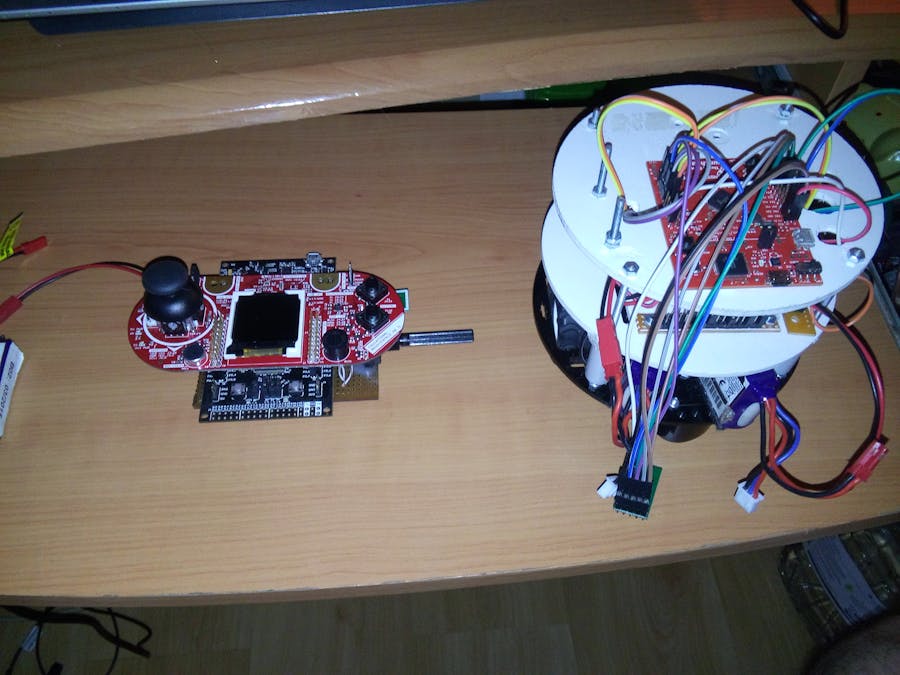
The car:
The car didn't change much through the project. Just a Tiva launchpad, a transceiver, a 5V regulator (the launchpad then has 3.3V regulator) , a DRV8833 motor driver, 2 motors, 2 encoders, 2 wheels and 2 casters, and of course the batteries and the base.
First the speed control had to be developed. I never really used enconders. Luckily the Tiva itself has a QEI, a hardware interface for the enconders. For that Tivaware was needed. It was real easy to set it up and then it would give me the speed, position and direction of the motors. I only used the speed and direction for this purpose, the speed I would then add the wheel perimeter and get the speed in cm/s. With tests I found in free run the motor could reach 200cm/s, though I usually capped it at 120 as it's maximum.
Then I applied a real simple PID, well a PI only. A little tweaking was needed, especially with the I.
The loop was so fast that the I would skyrocket the value. So instead of using Ki bellow 1, I used a counter to just increment the I every so often. This worked well.
Then I only need to make how the received data packets we're interpreted. That will be seen later.
The transmission packets
With that done I only needed to develop the packet sent through RF. I decided to be like a specific number, a command number (if in the future I want to add more), left motor direction, left motor speed, right motor direction and right motor speed.
So basically to set the robot moving forward at 50 speed it was {15, 3, 1, 50,1,50}.
Note that these are numbers, not char representations of numbers. So if I sent speed 0 so it would stop, it would not work. The number 0 represents the null terminator of string so the library would not send anything after that 0 - to solve this, 255 was gonna be the 0, 255 would mean that the speed sent for that motor was 0.
Now the direction, backwards and forward. That's with the 3rd and 5th numbers. 1 is forward. But -1 is not backwards - I instead used 2 for some reason and now I am just rolling with it.
The controller
Well the robot was simple. It just has to receive the motors speeds and deliver.
I wanted to use the new Educational Boosterpack MKII for this purpose. It seemed perfect with the components it has and the shape.
For controlling everything I first used a Tiva for testing, but that would consume too much power for a battery powered device like this. I wanted to use a MSP432 launchpad but there was some bugs on the Energia libraries for the LCD unfortunately. So the next best thing - a MSP430F5529 launchpad.
But let's see the developing again:
The controller is what needed some more features.
So first I started with the joystick.
Joystick control only
I tried to use the Y axis to control the speed and moving direction (forwards and backwards) of the robot while the X axis would control the turning.
Y was simple. Set the middle value, it should be around 2047. The just do Y_Value-MiddleValue. This will give you positive values when going forward and negative when going backwards. Convert that to a percentage: (Y_Value-MiddleValue)/2048 and you got something to multiply with the motors max speed, giving you control of the current speed like this.
If the percentage was negative, well then it's to go backwards.
Now the X. Note that this robot turns like a tank, not like a car. It doesn't have wheels that turn. You need to turn one wheel faster than the other to turn, or turn one wheel one way and the other wheel the other direction.
So for the turning I did the same method of getting a percentage. Exactly the same.
Now depending if the value was negative or positive, it would multiply one of the motors speed, reducing it.
If you pushed the joystick to the left, then the left motor goes slower, if you push it to the right, then the right motor goes slower.
I didn't like this type of control much. Because you don't have much control over both turning and speed. If you push the joystick forward too much, then you can't push it much to the sides - it's a circle it doesn't work that way.
Later I tested with the total radius controlling the speed instead of the Y axis. But Only after testing the next mode I am going to refer - reason why I also deprecated the radius speed control.
Add a potentiometer for the speed control
So I decided to add a pot to control the speed. The potentiometer is single turn and linear and gave a much bigger resolution and control than the joystick. The same math as the Y axis was used.
The only unfortunate thing is not springing back to the middle position.
The joystick X axis was still used for turning.
To avoid the robot going out of control the joystick button was used as a emergency stop. After a few moments you could press it again to go again.
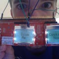
But it was hard to know if the speed was set to stop so it would not help that much. A LCD was used to give speed feedback to the user.
Tilt Modes>Then it was added 2 modes using a accelerometer.
The first you would control the whole thing with tilting. Tilt forward and backwards was to control the speed and direction the bot moved (forward or backwards). Tilting to the sides would tell it to turn.
The second tilt mode would use the joystick to move forward or backwards and the tilt would just control the steering. It was easier to use this tilt mode than the previous.
Add an LCD for feedback>I intended to use a TI boosterpack with a LCD, so why not use it to give feedback. It was most useful to give the speed set by the potentiometer but it also allowed for a selection menu for the desired control mode.
You can see here in the final product the very simple menu:
All this before getting the boosterpack generated this confusing prototype:
Integrate it all into a controller
Well the boosterpack arrived and it's easy to mount on top of the launchpad. But what about the 5V and 3.3V supply? The transceiver? And the pot?
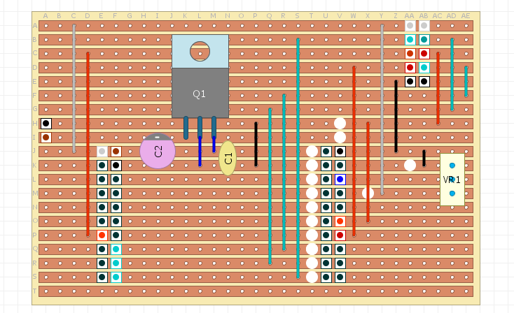
A little boosterpack had to be made:
After that is made it's time to mount it all:
And the final result:
Back boosterpack
It has a 5V regulator, a pot and a slot to mount the NRF24L01.
The final result actually also has a 3.3V regulator in TO-92 package, between the boosterpack pins. This was because the original design used the debugger 3.3V regulator, and later I decided that was a waste of power

Comments