/*
Arduino LANC<->RS232 interface
Version 1.0
For communicating with cameras via LANC
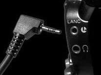
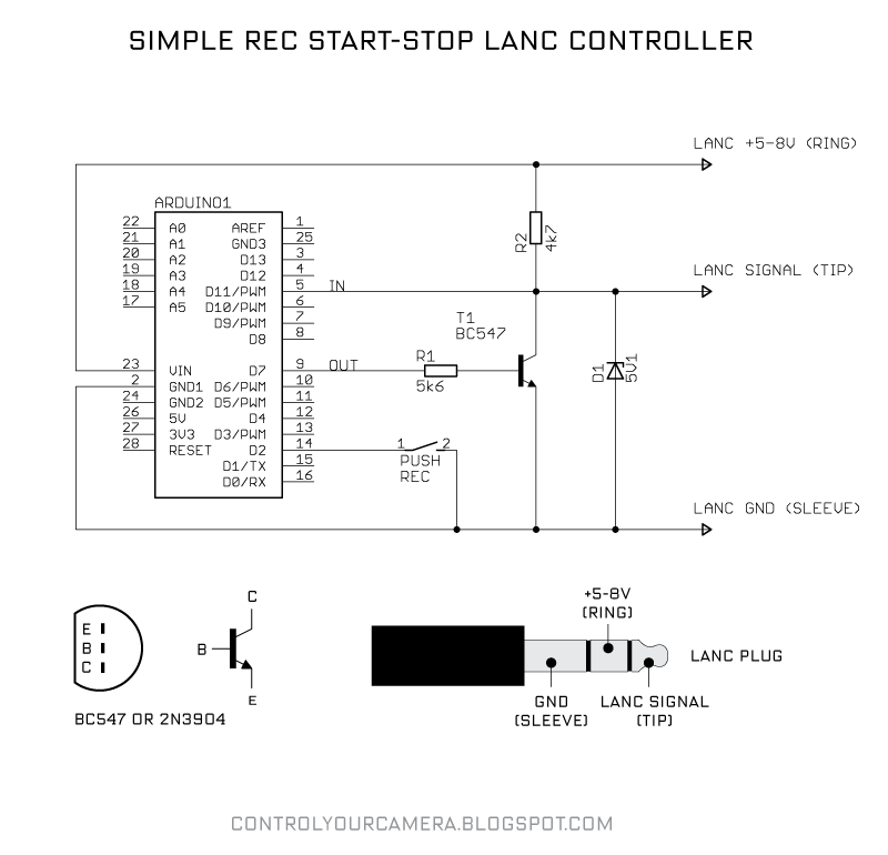
For the interface circuit interface see
http://controlyourcamera.blogspot.com/2011/02/arduino-controlled-video-recording-over.html
"LANC" is a registered trademark of SONY.
CANON calls their LANC compatible port "REMOTE".
Written by L.Rosén
------------------------------------------------------------------------------------------
Comments regarding service mode for Sony second generation D8 camcorders:
DCR-TRV8000E, DCR-TRV8100E, DCR-TRV120E, DCR-TRV125E, DCR-TRV320E, DCR-TRV325E
DCR-TRV420E, DCR-TRV520E, DCR-TRV620E, DCR-TRV725E
LANC message layout when reading/writing EEPROM(8 bytes each sent with LSB first)
B0 B1 B2 B3 B4 B5 B6 B7
B0 = First sent byte from our adapter
B1 = Second sent byte from our adapter
B2
B3
B4 = The 4 highest bits b7..b4 tells which page in the EEPROM you are at
B5 = Confirmation that the command has been received, read command confirmed with F0h, write commands confirmed with F1h
B6 = Tells which address in the EEPROM you are at
B7 = Data at address
The following commands is used to navigate the EEPROM and change data
B1 B2
FFh 00h = Read command, tells you current page:address:data without changing anything
FFh 67h = Increase page by 1
FFh 65h = Decrase page by 1
FFh 38h = Increase address by 1
FFh 36h = Decrase address by 1
FFh 34h = Increase data by 1
FFh 30h = Decrase data by 1
FFh 32h = STORE command
Metod for checksums (PAGE:ADDRESS:DATA):
1) enable changes in memory: 00:01:00 to 00:01:01 (Store)
2) change data on page D, how You need (all with STORE).
3) read new value:
"xx" from 02:F0
"yy" from 02:F1
4) enable update and visibility of checksums on (0F:FE and 0F:FF):
00:FF:00 -> 00:FF:02 (STORE)
00:01:01 -> 00:01:80 (STORE)
5) update new checksums:
write to address:
0F:FF data "xx" ( from 02:F0 ) (STORE)
0F:FE data "yy" ( from 02:F1 ) (STORE)
6) disable changes:
00:FF:02 -> 00:FF:00 (STORE)
00:01:80 -> 00:01:00 (STORE)
Links to more information:
http://lea.hamradio.si/~s51kq/DV-IN.HTM
http://www.sps.volyne.cz/set1394/anin/code20.html
------------------------------------------------------------------------------------------
*/
// The code uses fast I/O write because its time critical,
// therefore setting pins are done by writing directly to the registers:
#define cmdPinON (PORTD = B10000000) // Set digtal pin 7 (PD7)
#define cmdPinOFF (PORTD = B00000000) // Reset digtal pin 7 (PD7)
#define ledON (PORTB = B00100000) // Set LED pin 13 (PB5)
#define ledOFF (PORTB = B00000000) // Reset LED pin 13 (PB5)
#define lancPinREAD (PINB & B00001000) // Reads pin 11 (PB3)
#define lancPin 11
int bitDura = 104; // Duration of one LANC bit in microseconds, orginal 104
int halfbitDura = 52; // Half of bitDura
byte strPointer = 0; // Index when receiving chars
char inString[5]; // A string to hold incoming data
char outString[25]; // A string to hold outgoing data
boolean strComplete = false; // Indicator to see if the string is complete
boolean lancCmd[16]; // Array for the lancCmd in bits
boolean lancMessage[64]; // Array for the complete LANC message in bits
void setup() {
DDRD = DDRD | B10000000; // Config cmdPin as output
DDRB = DDRB & B11110111; // Config lancPin as input
DDRB = DDRB | B00100000; // Config ledPin as output
pinMode(lancPin, INPUT); // Listens to the LANC line, used for pulseIn function
cmdPinOFF; // Reset LANC control pin so that the LANC line is unaffected(HIGH)
Serial.begin(57600); // Start serial port
Serial.println("Welcome to the Arduino LANC-RS232 interface");
Serial.println("Send two bytes in hex form etc. 02AF and wait for reply from camera");
}
void loop() {
if (strComplete) { // inString has arrived
if (hexchartobitarray()) { // Convert hex chars to bitarray
sendLanc(4); // The LANC command needs to be repeated 4 times
bitarraytohexchar(); // Convert received bitarray to hex chars
for (int i=0; i<24 ;i++) { // Write back LANC message over serial
Serial.print(outString[i]);
}
Serial.print('\n');
}
else {
Serial.println("Faulty input!");
}
for (int i=0 ; i<5 ; i++) { // Clear input array
inString[i] = 0;
}
strComplete = false; // Reset data received flag
}
}
void bitarraytohexchar() {
// The bit array lancMessage contains the whole LANC message (8 bytes) with LSB first
// This function converts them to hex chars and stores them in outString (16 chars)
byte temp = 0;
for ( int i=0 ; i<8 ; i++) { // Byte loop
for ( int j=0 ; j<4 ; j++) { // Bit loop
temp += (pow2(j) * lancMessage[(j+4)+i*8]);
}
outString[i*3] = bytetohexchar(temp);
temp = 0;
for ( int j=0 ; j<4 ; j++) { // Bit loop
temp += (pow2(j) * lancMessage[j+i*8]);
}
outString[i*3+1] = bytetohexchar(temp);
outString[i*3+2] = ' ';
temp = 0;
}
outString[24] = '\n';
}
boolean hexchartobitarray() {
// The hex code in char (4 chars) is located in inString
// This function fills the lancCmd array with the bits in the order they should be sent
// First byte 1 then byte 2 but with LSB first for both bytes
int byte1, byte2;
for (int i = 0 ; i < 4 ; i++ ) {
if (!(isHexadecimalDigit(inString[i]))) {
return 0;
}
}
byte1 = (hexchartoint(inString[0]) << 4) + hexchartoint(inString[1]);
byte2 = (hexchartoint(inString[2]) << 4) + hexchartoint(inString[3]);
for (int i = 0 ; i < 8 ; i++ ) {
lancCmd[i] = bitRead(byte1,i); // Reads one bit from a number, x is number, n is position (0 is LSB)
}
for (int i = 0 ; i < 8 ; i++ ) {
lancCmd[i + 8] = bitRead(byte2,i); // Reads one bit from a number, x is number, n is position (0 is LSB)
}
return 1;
}
void sendLanc(byte repeats) {
// This function is time critical and optimized for Arduino Pro Mini
// It takes ~3.2us for the arduino to set a pin state with the digitalWrite command
// It takes ~80ns for the arduino to set pin state using the direct register method
// delayMicroseconds(50) ~ 49us, delayMicroseconds(100) ~ 99us
int i = 0;
int bytenr = 0;
while (pulseIn(lancPin, HIGH) < 5000) {
// Sync to next LANC message
// "pulseIn, HIGH" catches any 0V TO +5V TRANSITION and waits until the LANC line goes back to 0V
// "pulseIn" also returns the pulse duration so we can check if the previous +5V duration was long enough (>5ms) to be the pause before a new 8 byte data packet
}
while (repeats) {
i = 0;
bytenr = 0;
ledON; // LANC message LED indicator on
for ( ; bytenr<8 ; bytenr++) {
delayMicroseconds(bitDura-7); // LOW after long pause means the START bit of Byte 0 is here, wait START bit duration
for ( ; i<(8*(bytenr+1)) ; i++) {
if (bytenr<2) {
if (lancCmd[i]) { // During the first two bytes the adapter controls the line and puts out data
cmdPinON;
}
else {
cmdPinOFF;
}
}
delayMicroseconds(halfbitDura);
lancMessage[i] = !lancPinREAD; // Read data line during middle of bit
delayMicroseconds(halfbitDura);
}
cmdPinOFF;
if (bytenr == 7) {
ledOFF;
}
delayMicroseconds(halfbitDura); // Make sure to be in the stop bit before waiting for next byte
while (lancPinREAD) { // Loop as long as the LANC line is +5V during the stop bit or between messages
}
}
repeats--;
}
}
/*
SerialEvent occurs whenever a new data comes in the
hardware serial RX. This routine is run between each
time loop() runs, so using delay inside loop can delay
response. Multiple bytes of data may be available.
*/
void serialEvent() {
while (Serial.available()) {
char inChar = (char)Serial.read(); // Get the new byte
inString[strPointer++] = inChar; // Add it to the input string
if ((inChar == '\n') || (inChar == '\r') || (strPointer > 4)) { // If the incoming character is a newline, carriage return or 4 bytes has been received flag so the main loop can act
strComplete = true;
strPointer = 0;
}
}
}
int pow2(int x) {
switch (x) {
case 0:
return 1;
break;
case 1:
return 2;
break;
case 2:
return 4;
break;
case 3:
return 8;
break;
case 4:
return 16;
break;
case 5:
return 32;
break;
case 6:
return 64;
break;
case 7:
return 128;
break;
default:
return 0;
break;
}
}
char bytetohexchar(byte hexbyte) {
switch (hexbyte) {
case 15:
return 'F';
break;
case 14:
return 'E';
break;
case 13:
return 'D';
break;
case 12:
return 'C';
break;
case 11:
return 'B';
break;
case 10:
return 'A';
break;
default:
return (hexbyte + 48);
break;
}
}
int hexchartoint(char hexchar) {
switch (hexchar) {
case 'F':
return 15;
break;
case 'f':
return 15;
break;
case 'E':
return 14;
break;
case 'e':
return 14;
break;
case 'D':
return 13;
break;
case 'd':
return 13;
break;
case 'C':
return 12;
break;
case 'c':
return 12;
break;
case 'B':
return 11;
break;
case 'b':
return 11;
break;
case 'A':
return 10;
break;
case 'a':
return 10;
break;
default:
return (int) (hexchar - 48);
break;
}
}


_3u05Tpwasz.png?auto=compress%2Cformat&w=40&h=40&fit=fillmax&bg=fff&dpr=2)
Comments