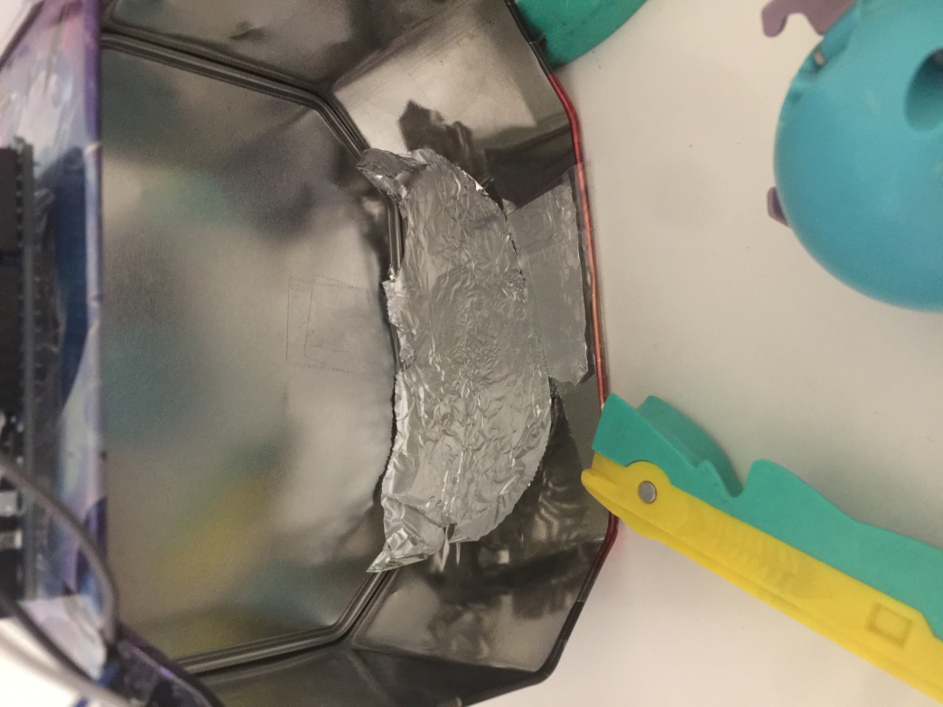
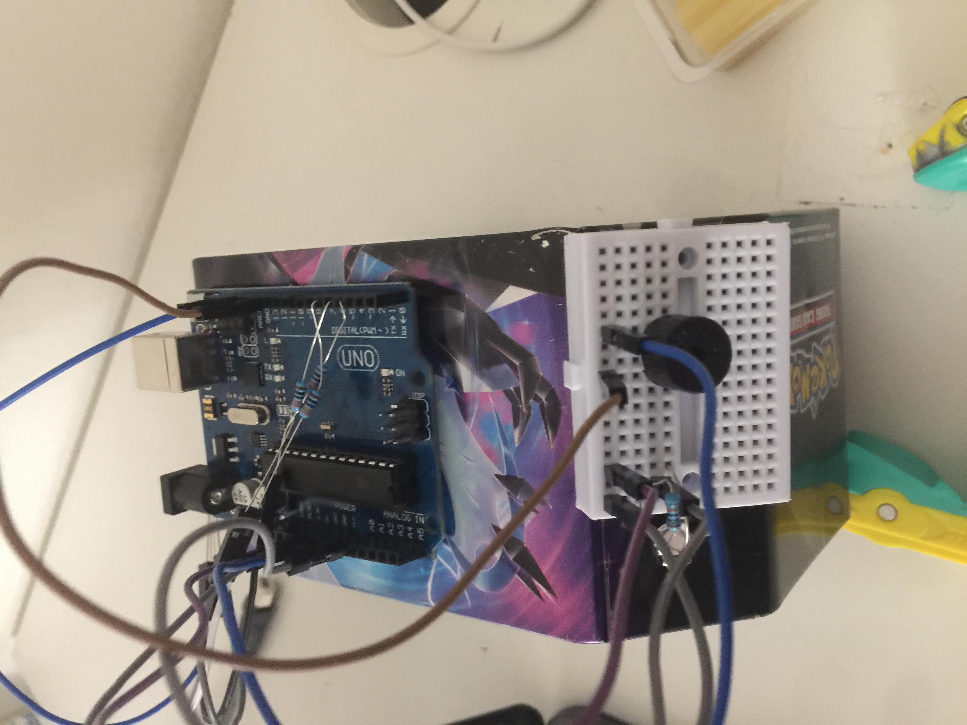
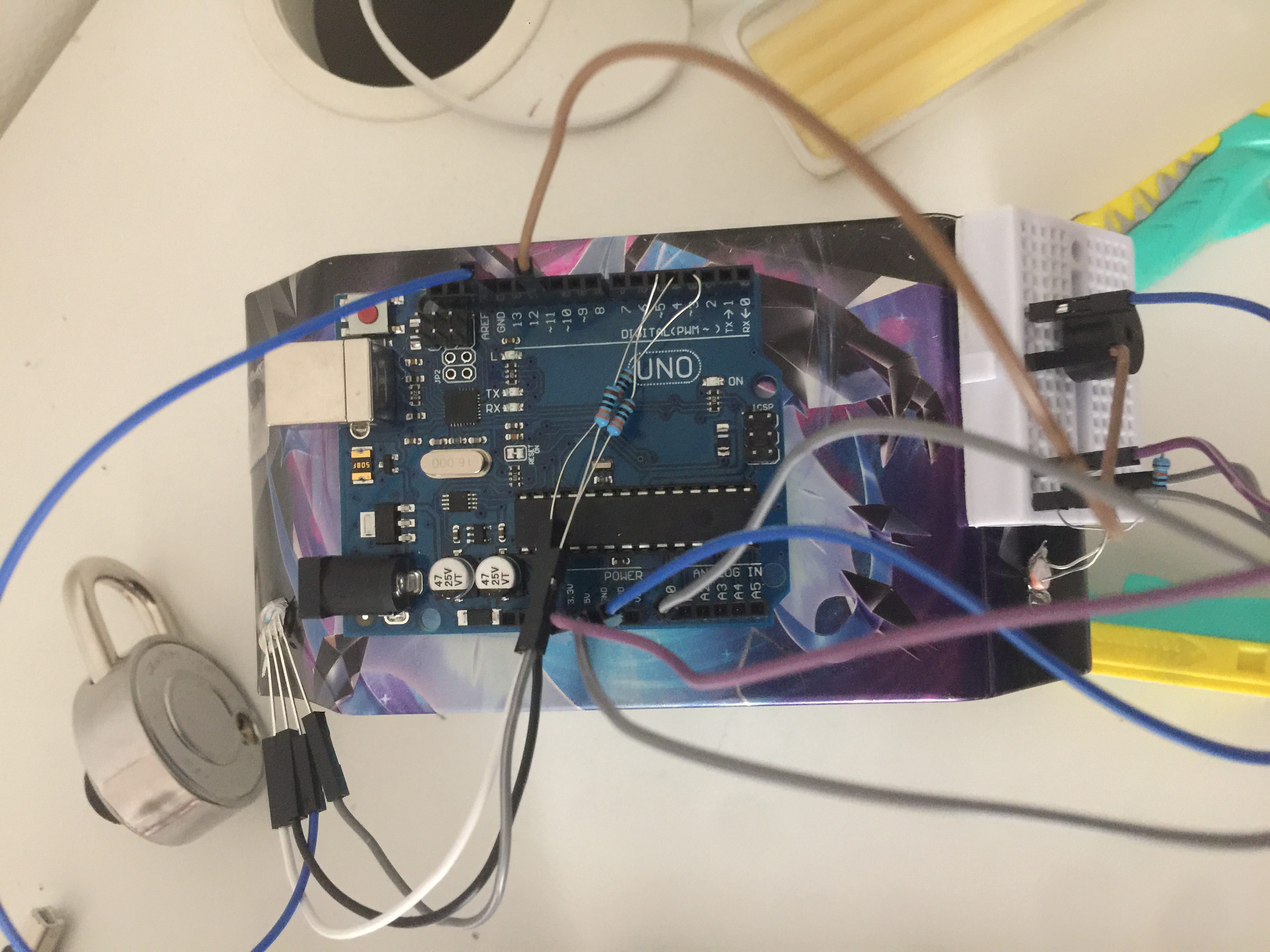
I think the LDR (light dependent resistor) is underrated and in my opinion it's a great thing, So basically what I've made is like a tin in which you keep your item and whenever someone picks it up, boom lights turn red and blue noises, Sound fun! Right?, Lets get into how it works...
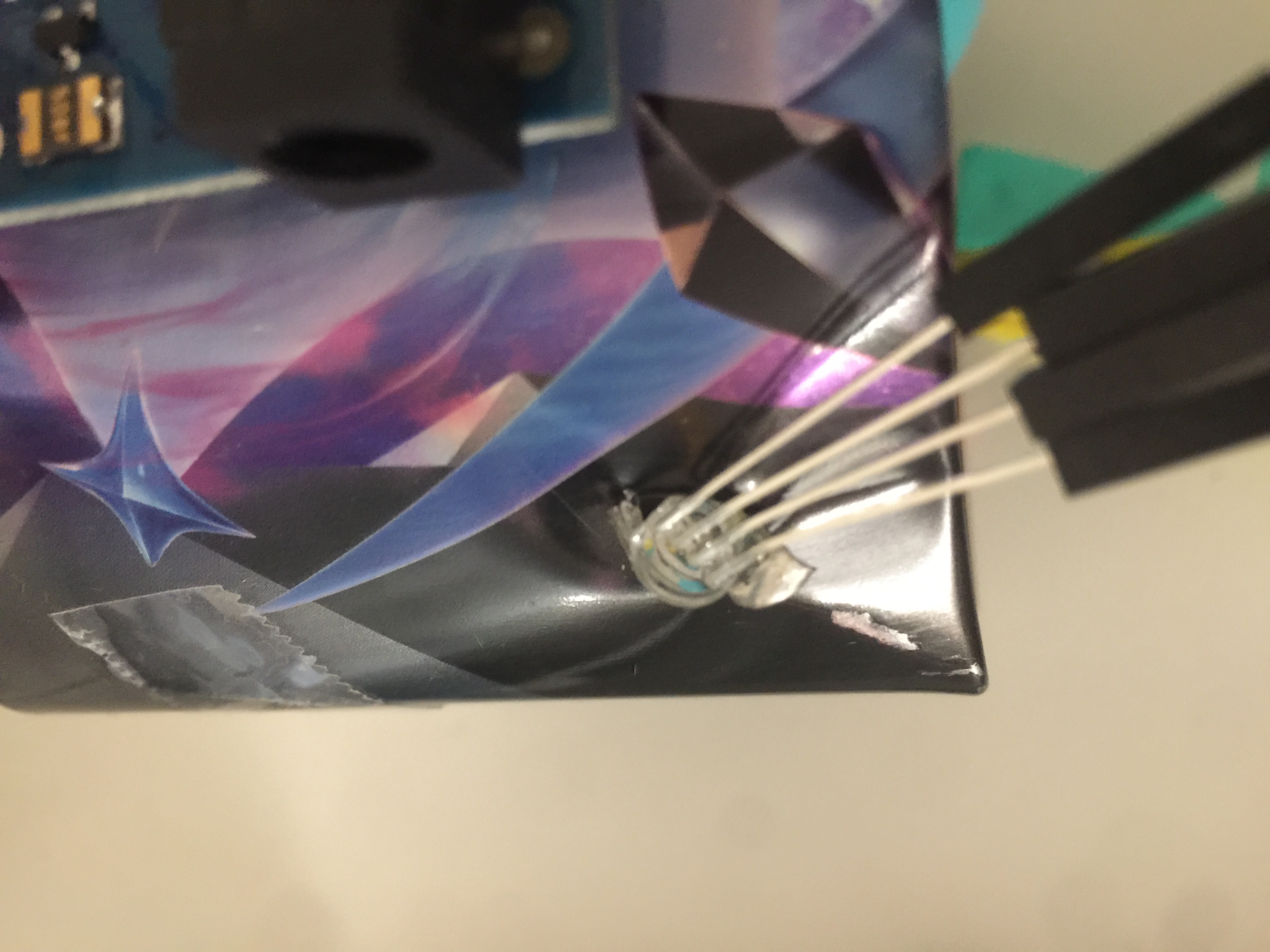
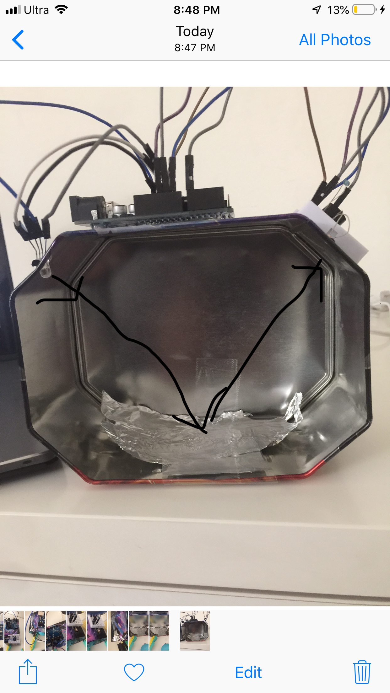
The Big ConceptThe ideas that the LDR picks up the amount light that is emitted through a RGB LED, which travels in a diagonal way and makes it's way to the LDR, but when it is obstructed with an object, the light cannot reach, so the LDR picks up low emissions, and then we program it so that if x amt. of light is emitted then something something happens else is y amt. is emitted and so on.


_ztBMuBhMHo.jpg?auto=compress%2Cformat&w=48&h=48&fit=fill&bg=ffffff)


Comments