


Hardware components | ||||||
_ztBMuBhMHo.jpg?auto=compress%2Cformat&w=48&h=48&fit=fill&bg=ffffff) |
| × | 1 | |||
 |
| × | 2 | |||
 |
| × | 4 | |||
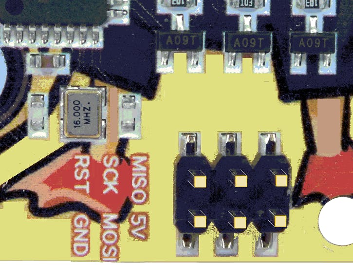
(As far as I know, the RGBDuino board shown above is the only ARDUINO clone with labels printed next to the SPI header.)
SPI is a fast protocol, but it could be much faster if used properly. What does that mean? Mostly you find code like this:
void transfer(byte x) {
  SPDR = x;
  while (!(SPSR & 0x80));
}
So, while waiting for the bits getting shifted out, the Arduino does nothing at all.
The PrincipleBut reading the data sheet you find not only in slave mode but also in master mode you can set the SPIE (SPI interrupt enable) bit in the SPCR (SPI control register).
This is only a first study to make sure it really works; more studies have to be done. Have a look at this:
/*
  exploring the SPI ISR routine
  intentionally, no libraries were used
*/
void setup() {
  Serial.begin(9600);
  Serial.println(__FILE__);
  // do not swap those lines!
  DDRB = B00101100; // SCK + MOSI + CS
  SPCR = B11010000; // SPIE + SPE + MaSTeR
  // Bit 7 = SPIE: SPI Interrupt Enable!
  // connect two buttons to pins 2 and 3:
  pinMode(2, INPUT_PULLUP);
  pinMode(3, INPUT_PULLUP);
  // connect four LEDs to pins 7 - 10:
  pinMode(7, OUTPUT);
  pinMode(8, OUTPUT);
  pinMode(9, OUTPUT);
  pinMode(10, OUTPUT);
}

/*
  writing data to SPDR will cause sending this
  on completion the SPI ISR will be called.
  Press button-2 to switch LED-7 on,
  press button-3 to switch LED-7 off.
*/

volatile boolean v;
volatile byte pinNr;

void loop() {
  if (digitalRead(2) == LOW) {
    v = HIGH;
    pinNr = 7;
    SPDR = 4; // send anything
    while (digitalRead(2) == LOW);
  }
  if (digitalRead(3) == LOW) {
    pinNr = 7;
    v = LOW;
    SPDR = 4; // send anything
    while (digitalRead(3) == LOW);
  }
}

ISR(SPI_STC_vect) {
  if (pinNr > 10) return;
  digitalWrite(pinNr, v);
  pinNr++;
  SPDR = 5; // send anything
}
If you press button-2, a boolean variable is set to HIGH and some data are sent via SPI. As soon as data transmission is completed, an SPI interrupt is invoked and the ISR starts working switching an LED on and sending more data. Again, when transmission is completed, the ISR itself is called another time. Eventually, it will stop (return) when no more LEDs can be switched on.
The four LEDs in this example will be switched on or off one after the other but so fast that you cannot see it.
The opposite will happen when button-3 is pressed.
This very simple example shows how interrupts can be used with the SPI protocol in the Arduino environment.
A simple ApplicationNow let us turn it into a useful project. There is a nice 8-digit LED display which is controlled by a MAX7219 chip offered by many distributers. Of course, there is a library to use it but this time we go without.
On the left side of the display there are five pins to connect: power, DIN = MOSI, CS and CLK = SCK. All can be connected to the SPI header except CS. Have a close look at the code:
/*
  version with array
*/

#define DEB-UG

const byte LOAD_PIN = 10;

void setup() {
  Serial.begin(9600);
  Serial.println(__FILE__);
  // do not swap those lines!
  DDRB = B00101100; // SCK + MOSI + CS
  // mode = 0: CPOL = 0, CPHA = 0
  SPCR = B01010000; // SPE + MaSTeR
  // Bit 7 = SPIE: SPI Interrupt Enable
  maxTransfer(0x0F, 0x01); // All segments should light up
  delay(100);
  maxTransfer(0x0F, 0x00);
  maxTransfer(0x09, 0xFF); // Enable decode mode B
  maxTransfer(0x0A, 0x05); // set intensity
  maxTransfer(0x0B, 0x07); // scan n+1 digits
  maxTransfer(0x0C, 0x01); // Turn on chip
}

long n = 10000000;
byte buff[16];
byte countLoop;
volatile byte countISR;

void loop() {
  static long dez[] = {1E7, 1E6, 1E5, 1E4, 1E3, 100, 10};
  // static saves time!
  // --- this is ltoa at dobble speed --- :
  byte v;
  // prepare buffer
  long n1 = n;
  countLoop = 0;
  for (byte i = 0; i < 7; i++) {
    long dezi = dez[i];
    for (v = -1; n1 >= 0; n1 = n1 - dezi, v++);
    if (i == 4) v = v + 128; // set dp at pos. 4
    writeToBuff(8 - i, v); // write all but the last one
    n1 = n1 + dezi;
  }
  writeToBuff(1, n1); // remainder
#ifdef DEBUG
  for (int i = 0; i < 16; i++) {
    Serial.print(buff[i]);
    Serial.print(" ");
  }
  Serial.println(" <-- loop");
#endif
  //--------------------------------------
  // enable ISR to work:

  SPCR = SPCR | 0x80; // SPIE: SPI Interrupt Enable

  digitalWrite(LOAD_PIN, LOW); // Ensure LOAD/CS is LOW
  countISR = 0;
  SPDR = buff[countISR++]; // send the first byte

  n++;
  if (n > 10100000) {
    Serial.println(n);
    Serial.println(millis());
    while (true);
  }
#ifdef DEBUG
  delay(1000);
#endif
}

//---------------------------------------------
// __vector_17
ISR(SPI_STC_vect) {
  // this is called when the previous transfer is completed
  if ( (countISR & 1) == 0) {
    asm("sbi 5,2"); // set CS to HIGH
    if (countISR >= 16) {
#ifdef DEBUG
      Serial.println(countISR);
      Serial.println( "<-- ISR");
#endif
      SPCR = SPCR & 0x7F; // clear SPIE, no more interrupts
      return;
    }
  }
  asm("cbi 5,2"); // Ensure LOAD/CS is LOW
  byte v = buff[countISR];
#ifdef DEBUG
  Serial.print(v);
  Serial.print("_");
#endif
  SPDR = v; // send next byte
  countISR++;
}

void writeToBuff(byte address, byte value) {
  buff[countLoop++] = address;
  buff[countLoop++] = value;
}

void maxTransfer(byte address, byte value) {
  // only called in setup, no need to speed-up
  digitalWrite(LOAD_PIN, LOW); // set CS to LOW
  SPDR = address;
  while (!(SPSR & 0x80));
  SPDR = value;
  while (!(SPSR & 0x80));
  digitalWrite(LOAD_PIN, HIGH); // set CS to HIGH
}
The setup() is executed only once so not speed-up has to be performed. The loop just counts from 10,000,000 to 10,100,000 so all eight digits are affected but it will not take too much time. The first thing you might notice is we did not use itoa or ltoa to convert the integer value to decimal but replaced by a faster algorithm. The MAX7219 always wants position and value so 16 bytes have to be sent to display 8 digits. Now the left-most value is sent to the SPI device which will trigger the ISR. Inside the ISR it has to be checked if it is position or value to handle the CS pin properly. When all bytes have been sent the SPIE bit has to be cleared to prevent more interrupt calls until new data have to be displayed.
Still too slow? - Use Assembler!We noticed that the ISR has to be called for each single byte, and the GCC compiler enjoys pushing an popping whatever it can. So when we check what is really needed you can save another 15 percent of the time required and about twice the speed without ISR.
[code]
/*
  version with array and inline assembler
*/

const byte LOAD_PIN = 10;

void setup() {
  Serial.begin(9600);
  Serial.println(__FILE__);
  // do not swap those lines!
  DDRB = B00101100; // SCK + MOSI + CS
  // mode = 0: CPOL = 0, CPHA = 0
  SPCR = B01010000; // SPE + MaSTeR
  // Bit 7 = SPIE: SPI Interrupt Enable
  maxTransfer(0x0F, 0x01); // All segments should light up
  delay(100);
  maxTransfer(0x0F, 0x00);
  maxTransfer(0x09, 0xFF); // Enable decode mode B
  maxTransfer(0x0A, 0x05); // set intensity
  maxTransfer(0x0B, 0x07); // scan n+1 digits
  maxTransfer(0x0C, 0x01); // Turn on chip
}

long n = 10000000;
byte countLoop;
volatile byte countISR;
byte buff[16];

void loop() {
  static long dez[] = {1E7, 1E6, 1E5, 1E4, 1E3, 100, 10};
  // static saves time!
  // --- this is ltoa at dobble speed --- :
  byte v;
  // prepare buffer
  long n1 = n;
  countLoop = 0;
  for (byte i = 0; i < 7; i++) {
    long dezi = dez[i];
    for (v = -1; n1 >= 0; n1 = n1 - dezi, v++);
    if (i == 4) v = v + 128; // set dp at pos. 4
    writeToBuff(8 - i, v); // write all but the last one
    n1 = n1 + dezi;
  }
  writeToBuff(1, n1); // remainder
  //--------------------------------------
  // enable ISR to work:

  SPCR = SPCR | 0x80; // SPIE: SPI Interrupt Enable

  digitalWrite(LOAD_PIN, LOW); // set CS to LOW
  countISR = 0;
  SPDR = buff[countISR++]; // send the first byte

  n++;
  if (n > 10100000) {
    Serial.println(n);
    Serial.println(millis());
    while (true);
  }
}

//---------------------------------------------
ISR(SPI_STC_vect, ISR_NAKED) {
  asm("push r0 \n\t"
      "in r0, __SREG__  \n\t"
      "push r30         \n\t"
      "push r31         \n\t"
      "lds r30, %0      \n\t" // countISR
      "sbrc r30, 0      \n\t" // skip 1 instr if bit is clear
      "rjmp continue    \n\t" // jump to continue
      "sbi 5,2 \n\t"
      "cpi r30, 16      \n\t" // countISR > 16 ?
      "brcs continue    \n\t"
      "in r30, %1       \n\t"
      "andi r30, 0x7F   \n\t" // clear SPIE, no more interrupts
      "out %1, r30      \n\t"
      "rjmp ende        \n\t"
      "continue:        \n\t"
      "cbi 5,2          \n\t"
      "ldi r31, 0       \n\t"
      "subi r30, lo8(-(buff)) \n\t"
      "sbci r31, hi8(-(buff)) \n\t"
      "ld r30, Z        \n\t"
      "out %2, r30      \n\t" // SPDR = buff[countISR]
      "lds r30, %0      \n\t" // countISR
      "subi r30, 255    \n\t" // + 1
      "sts %0, r30      \n\t"
      "ende:            \n\t"
      "pop r31          \n\t"
      "pop r30          \n\t"
      "out __SREG__, r0 \n\t"
      "pop r0           \n\t"
      "reti             \n\t"
      : "=X" (countISR) // %0:
      : "M" (_SFR_IO_ADDR(SPCR)), // %1:
      "M" (_SFR_IO_ADDR(SPDR))  // %2:
     );
}

void writeToBuff(byte address, byte value) {
  buff[countLoop++] = address;
  buff[countLoop++] = value;
}

void maxTransfer(byte address, byte value) {
  // only called in setup, no need to speed-up
  digitalWrite(LOAD_PIN, LOW); // set CS to LOW
  SPDR = address;
  while (!(SPSR & 0x80));
  SPDR = value;
  while (!(SPSR & 0x80));
  digitalWrite(LOAD_PIN, HIGH); // set CS to HIGH
}
[/code]
The FLASH usage is only 2600 bytes. Be careful when you edit this code.

_3u05Tpwasz.png?auto=compress%2Cformat&w=40&h=40&fit=fillmax&bg=fff&dpr=2)
Comments