


Hardware components | ||||||
 |
| × | 1 | |||
 |
| × | 1 | |||
| × | 1 | ||||
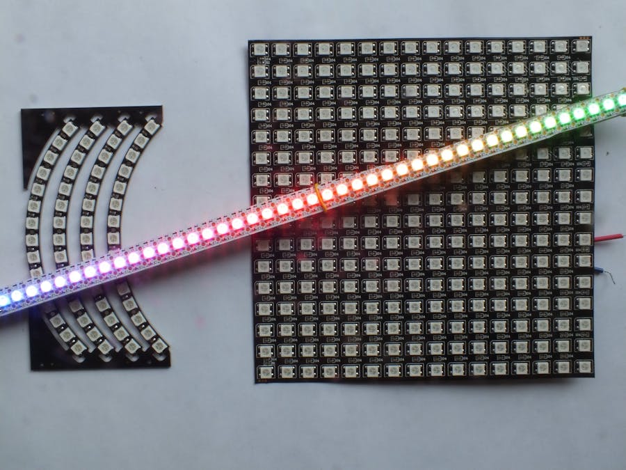
Is it really necessary to add more applications using the WS2812B strips? Well, not really, but playing with the strips gives so much fun, I could not resist.
Finding the LED numbers inside the 16x16 squareAt a first view, you will find it difficult to locate certain LEDs.
Using this formula will give you all the LED numbers.
How to determine the actual strip lengthJust a short note before I start:
In many cases you might use the ARDUINO-Vcc as a power supply for your LED strip and it will work pretty well. When I used an ARDUINO clone equipped with the CH340 chip and selected high baud-rates (above 38400) data sent to the Serial monitor or Serial plotter became corrupted. Especially on the Serial plotter you would notice immediately that something is going wrong. To avoid this, I had to use a separate power supply for the strip.
WS2812 strips come in lengths of 30, 60, 120, 144, 256, 300 and even others. But sometimes you might cut a string at some position, or one of the LEDs will bourn-out, leaving the remaining string unaddressable. You can always count the LEDs, but how can an Arduino detect that number? Well, I was surprised to find that at the data pin Din you can read a voltage that depends on the number of LEDs that are switched on. Of course, before reading, you have to set that pin to INPUT mode, and do not forget to turn it to OUTPUT again after reading. As soon as none of the existent LED are on, the voltage does not change any more:
As you can see, after the last exiisting LED has been addressed the voltage does not drop any further. Obviously, in this case I used two strips of 60 LEDs.
So, by using this more than simple "schematics" and algorithm, the Arduino can find the last existent pixel number.
"Schematics":
- WS2812-GND to Arduino-GND
- WS2812-Din to Arduino-A5
- WS2812-Vcc to Arduino-Vcc.
/*
  This program will measure the actual length of your LED strip.
  Mit diesem Programm kannst du "messen", wie viele RGB-LEDs dein WS2812-Strip hat.
  Update: 13.8.23
  -------------------------------------------
  Bestimmung der Laenge eines RGB-LED-Strips:
  Im Programm werden stets nur einige LEDs aktiviert, sofern ueberhaupt vorhanden.
  Hardware:
  1 x ARDUINO
  1 x WS2812B-Strip any length, beliebiger Laenge
  Wires/Kabel:
  ARDUINO-GND ---> WS2812-GND
  ARDUINO-Vcc ---> WS2812-Vcc
  ARDUINO-A5  ---> WS2812-Din

  Results:
  surprising fact:
  the voltage read back at Din when set to INPUT mode
  depends on the number of LEDs that are lit.
  In the Serial Plotter you can see these steps.
  Ergebnis:
  die Spannung, die an Din (als Eingang gesetzt)
  gemessen wird, ist abhaengig von der Zahl der LEDs,
  die leuchten.
  Im Seriellen Plotter kannst du genau
  sehen, nach dem wievielten Schritt
  das der Fall ist.
*/
const byte PIN = A0; // or any other analog pin
const int NUMPIXELS = 500; // width of the Serial Plotter
const long WHITE = 0xFFFFFF;

#include <Adafruit_NeoPixel.h>
Adafruit_NeoPixel strip = Adafruit_NeoPixel(NUMPIXELS, PIN, NEO_GRB + NEO_KHZ800);

void setup() {
  Serial.begin(115200);
  Serial.println(__FILE__ "0 0\nmillivolts");
  Serial.println("0\t-2");
  strip.begin();
  for (int i = 1; i < NUMPIXELS - 1; i++) {
    strip.clear();
    for (int j = 0; j < 100; j = j + 5)
      strip.setPixelColor(i + j, WHITE);
    strip.show();
    /*
      read actual voltage several times, calculate average
      miss die aktuelle Spannung mehrfach, berechne Mittelwert
    */
    int N = 5;
    long u = 0;
    pinMode(PIN, INPUT);
    for (int j = 0; j < N; j++)
      u = u + analogRead(PIN);
    // millivolts:
    float v = 5.0 * u / N;
    v = constrain(v, 0, 10);
    Serial.print(v);
    Serial.print(" \t ");
    // tickmarks every 10 numbers:
    if ((i % 100) == 0) Serial.println(-2);
    else if ((i % 10) == 0) Serial.println(-1);
    else Serial.println(0);
    pinMode(PIN, OUTPUT);
  }
}

void loop() {}
To test this program I cascaded a couple of these short strips:
Actually, I recently found an article on the same matter, published already in 2014, see: https://cpldcpu.wordpress.com/2014/11/16/ws2812_length/
How to make the strip length adjustableGiven you want to adapt your program to strips of different lengths without rewriting your code again and again, how can it be done?
Well, Adafruit provides a function called updateLength(NUMPIXELS). This is how it can be used easily: each ARDUINO is eqipped with a RESET button. Just repeat pressing the RESET button until you reach the correct strip length. A list of common strip lengths is provided. This examples just shows random colors plus R-G-B at both ends of the selected range. The comparison with PI guaranties that a disruption of power will not modify your selection.
Footnote: in the constructor, a strip length of 300 is required. This only works as long as the rest of your program leaves enough memory to drive 300 LEDs.
/*
  How to set the actual length of a WS2812 LED string
  No extra components needed,
  just the internal RESET button.
*/
// =============================================
#include <EEPROM.h>
// using EEPROM[0] to store value of index
// check for POWER_ON, PI in memory very unlikely
float pi __attribute__ ((section(".noinit")));
// program upload does not affect EEPROM.
const int sl[] = { 30, 44, 60, 120, 144, 300 };
const byte SL = sizeof sl / sizeof(int);
int index, NUMPIXELS;
// index is only modified if RESET button is pressed
// =============================================

#include <Adafruit_NeoPixel.h>
const byte PIN = A5;
Adafruit_NeoPixel strip = Adafruit_NeoPixel(300, PIN, NEO_GRB + NEO_KHZ800);
const long RED = 0xFF0000;
const long GREEN = 0x00FF00;
const long BLUE = 0x0000FF;

void setup() {
  Serial.begin(9600);
  // =============================================
  index = EEPROM.read(0);
  if (pi != PI) Serial.println("\nPower On");
  // coldstart detected, accept old index
  else if (++index >= SL) index = 0;
  EEPROM.update(0, index);
  pi = PI; // enables to detect a warmstart
  NUMPIXELS = sl[index];
  Serial.print("number of pins: ");
  Serial.println(NUMPIXELS);
  // =============================================
  strip.begin();
  strip.setBrightness(50);
  strip.show();
  strip.updateLength(NUMPIXELS);
}

void loop() {
  strip.setPixelColor(0, RED);
  strip.setPixelColor(1, GREEN);
  strip.setPixelColor(2, BLUE);
  // some random colors:
  for (int i = 3; i <= strip.numPixels() - 4; i++)
    strip.setPixelColor(i, random(0xFFFFFF));
  strip.setPixelColor(strip.numPixels() - 3, RED);
  strip.setPixelColor(strip.numPixels() - 2, GREEN);
  strip.setPixelColor(strip.numPixels() - 1, BLUE);
  strip.show();
  delay(200);
}It can be calculated easily: for each LED you will need 3 Bytes. Plus some housekeeping of course.
How do I know if some extra long strips fit into memory? The Adafruit Neopixel functions do not give you any error message if it does not. Well, you will see nothing is going to be shown on the strip if the memory requirements exceed your free RAM. In your sketch you can check the function strip.numPixels(). It will return zero if it does not fit. Otherwise it will return NUMPIXELS.
Power requirementsIf you use a strip longer than 60 LEDs or drive the LEDs very bright, near to white, you cannot go any longer with USB power. Using a square 16x16 device, I measured the current as a function of the number n of LEDs. I found these formulas:
I (mA) = n * 40 + 300 for color = WHITE and
I (mA) = n * 13.25 + 250 for color = 0x555555
When using a DC power adapter, connect all the GROUND pins, connect the positive to the 5V pin of the strip and connect the data-out of the Arduino to Din of the strip. When programming of the Arduino is done, you can run it stand-alone connecting the 5V of the Arduino to 5V of the strip; you do not need a second power adapter to power the Arduino.
How can I measure the time required to send the show() command?It is understood that all the other commands (begin, clear, setPixel) do not take much time. What about show(), when all the data are sent to the first LED, passing them to the next LED and so on? If you read the millis() or micros() before and after, the results will be nearly the same. How can that be? The answer is: the WS2812 protocol needs a very strict timing, and any interrupts in the Arduino environment would disturb it completely. So, when the send() command is invoked, all interrupts get disabled and get only reenabled after completion of this command. So even TIMER0 won't be able to update millis() and micros(). If you still want to check the time, you need to send "markers" to a second Arduino which can evaluate the time interval. If your sketch relies on correct timing you have to take this into account. For correct time-keeping better connect to an RTC chip.
This sketch will send time markers through pin-8 before and after performing show():
/*
  for any number of pixels checking
  the time to perform "show" always
  would give you something near zero.
  So you need an external device
  for measurment.
*/
const byte PIN = A0;
const int NUMPIXELS = 120;
const long WHITE = 0xFFFFFF;

#include <Adafruit_NeoPixel.h>
Adafruit_NeoPixel strip = Adafruit_NeoPixel(NUMPIXELS, PIN, NEO_GRB + NEO_KHZ800);

void setup() {
  strip.begin();
  strip.clear();
  // set pixel in the middle:
  strip.setPixelColor(NUMPIXELS / 2, WHITE);
  pinMode(8, OUTPUT);
  digitalWrite(8, HIGH);
  // now send date to all of the LEDs:
  strip.show();
  digitalWrite(8, LOW);
}

void loop() {}
This sketch will watch the time markers it receives at pin-8 and print the result on the Serial monitor:
/*
  To measure the time the first Arduino
  takes to perform the procedure,
  connect pin-8 of this Arduino to pin-8
  of the sending Arduino.
*/

void setup() {
  Serial.begin(115200);
  Serial.println(__FILE__);
  while (digitalRead(8) == LOW);
  long t1 = micros();
  while (digitalRead(8) == HIGH);
  long t2 = micros();
  Serial.print(t2 - t1);
  Serial.println(" micro seconds");
}

void loop() {}
As the WS2812 datasheet is telling us, at a frequency of 800 kHz one bit will take 1.25 microseconds. So, 24 bits will take 30 micro seconds. When you compare the results given by the second program you will find an overhead of about 200 micro seconds for some housekeeping.
In case you drive a string of 60 LEDs, with each show() command you loose more than 1.8 milliseconds. If you update a ring of 60 LEDs once a second to simulate an analog clock you loose more than 155 seconds in one day, that is nearly three minutes!
From one end to the other: Din-DOAs you know, as soon as an LED has received data ment for itself it will pass any subsequent input data to the next one(s), not knowing if there are any. So, when you declare a number that exceeds the number of the actual existing LEDs subsequent pulses are sent to a wire leading to nowhere. This is the code to send 45 packets of data to a string of only 44 LEDs:
const byte PIN = A5;
const int NUMPIXELS = 45;
const long WHITE = 0xFFFFFF;

#include <Adafruit_NeoPixel.h>
Adafruit_NeoPixel strip = Adafruit_NeoPixel(NUMPIXELS, PIN, NEO_GRB + NEO_KHZ800);

void setup() {
  strip.begin();
}

void loop() {
  strip.show();
}
To examine what is output of the last LED, I fed the input data of the first LED and the Dout of the last LED to a 2-beam scope, trigger set to Y2.
When I set the number of LEDs to the correct value nothing is shown on the Y2 beam. Beam Y1 also confirms transmission of 45 packets of data takes 45x30µs = 1.35 ms as expected.
When I increased the resolution I got this picture:
Trigger was set to Y2. The picture shows the 24 pulses sent by the last LED to nowhere. On Y1 there are only 18 pulses visible. Obviously, there is a short delay between input and output data.
You can find more analysis on Tim's blog.
A rainbow with some special effectsWhile there is a built-in rainbow function included in the library, it can be done easily with just a few lines of code:
const byte A = 2;
const byte B = 3;
const byte C = 4;
float r = p(abs(x - B) - 1);
float g = p(2 - abs(x - A));
float b = p(2 - abs(x - C));
strip.setPixelColor(pixno, r, g, b);
where pixno is the number of the current pixel and the function p is defined like this:
// auxiliar for rainbow:
float p(float x) {
if (x > 0) return x * 17;
return 0;
}
In the following example, the rainbow runs downwards while some spots slowly climb upwards but then drop to the bottom rapidly:
#include <Adafruit_NeoPixel.h>
const  byte PIN = A5;
const byte NUMPIXELS = 44;
Adafruit_NeoPixel strip;
int ofs = 0;
struct climber {
float x;
long color;
boolean up = true;
} R, G, Bl; // cannot use "B"
void setup() {
strip = Adafruit_NeoPixel(NUMPIXELS, PIN, NEO_GRB + NEO_KHZ800);
strip.begin();
R.x = 0;
R.color = 0xFF0000;
G.x = NUMPIXELS / 3;
G.color = 0x00FF00;
Bl.x = NUMPIXELS * 2 / 3;
Bl.color = 0x0000FF;
}
void loop() {
// rainbow:
handleRainbow();
// climbers:
handleClimber(&R);
handleClimber(&G);
handleClimber(&Bl);
strip.show();
delay(50);
}
void handleRainbow() {
const byte A = 2;
const byte B = 3;
const byte C = 4;
const float D = 6;
for (int pixno = 0; pixno < NUMPIXELS; pixno++) {
float x = (pixno + ofs) * D / NUMPIXELS;
while (x < 0) x = x + 6;
while (x > 6) x = x - 6;
float r = p(abs(x - B) - 1);
float g = p(2 - abs(x - A));
float b = p(2 - abs(x - C));
strip.setPixelColor(pixno, r, g, b);
}
if (++ofs > NUMPIXELS) ofs = 0;
}
// auxiliar for rainbow:
float p(float x) {
if (x > 0) return x * 17;
return 0;
}
void handleClimber(climber * c) {
float cx = c->x;
long color = c->color;
strip.setPixelColor(cx, color);
strip.setPixelColor(cx + 0.7, color);
strip.setPixelColor(cx + 1.4, color);
if (c->up)
c->x = cx + 0.2; // upwards slowly
else
c->x = cx - 4; // downwards fast
// change direction:
if (cx > NUMPIXELS) c->up = false;
if (cx <= 0) c->up = true;
}The color of the real mercury was like silver; but with the RGB LEDs I can color it blue for low tmperatures and red for hot temperatures. The problem is how to indicate the tickmarks, because you cannot print figures. I decided to show white LEDs at whole numbers and show even two adjacent LEDs at numbers divisable by five. LEDs would lit from the bottom up to the LED correspondending to the current temperature, all the rest of the LEDs would just show minimum brightness. A problem to be solved was how to handle values which are equal to the tickmarks. The solution was to show the proper color and the white tickmark alternatively. As white turned out to be too bright it had to be replaced by gray.
The Arduino used was a PRO-MINI, the sensor used was a DS18B20 type connected to pin 10 (powered by pins 8 and 9, and the strip was a 144-LED-type connected to pin 0 aka RX. The temperatur range was from 15.0°C to 29.4°C.
/*
  Thermometer using DS18B20 and WS2812B
  ------------------------------------
  Column from cold = blue to warm = red
  LEDs up to the actual temperature ar shown
  bright, the rest of the LEDs much darker.
  When the actual temerature equals a tickmark
  this LED is shown blinking.
*/

#include <DallasTemperature.h>
const byte GND = 8;
const byte Vcc = 9;
const byte ONE_WIRE_BUS = 10;
OneWire oneWire(ONE_WIRE_BUS);
DallasTemperature sensors(&oneWire);
const int T1 = 15; // Grad Celsius
const int dt = 10; // Pixels per Grad

#include <Adafruit_NeoPixel.h>
const long NUMPIXELS = 144;
byte PIN = 0; // A5; // 0 for PRO-MINI/Lilypad
const long GRAY = 0x808080;

Adafruit_NeoPixel strip;

byte saturation = 255;
byte hell = 100;
byte dunkel = 3;
boolean blink;

void setup() {
  Serial.begin(9600);
  Serial.println(__FILE__);
  if (PIN == 0) Serial.end(); // conflikt
  // sensor:
  pinMode(GND, OUTPUT);
  pinMode(Vcc, OUTPUT);
  digitalWrite(Vcc, HIGH);
  sensors.begin();
  delay(700);
  // display:
  strip = Adafruit_NeoPixel(NUMPIXELS, PIN, NEO_GRB + NEO_KHZ800);
  strip.begin();
  Serial.println("Start");
}

void loop() {
  sensors.requestTemperatures();
  float temp = sensors.getTempCByIndex(0);
  int num = tempToPixNum(temp);
  Serial.print(temp);
  Serial.print(" ");
  Serial.println(num);
  // the thermometer-column:
  for (int i = 0; i <= num; i++)
    strip.setPixelColor(i, color(i, hell));
  for (int i = num + 1; i < NUMPIXELS; i++)
    strip.setPixelColor(i, color(i, dunkel));
  // die "Skale text"
  for (int T = T1; T < T1 + 2 * dt; T++) {
    int n = tempToPixNum(T);
    setTick(n, num);
    // double points, when T divisable by 5 :
    if (T % 5 == 0) setTick(n + 1, num);
  }
  strip.show();
  blink = !blink;
}

int tempToPixNum(float temp) {
  return dt * (temp - T1);
}

long color(byte i, byte brightness) {
  word hsv = (NUMPIXELS - i) * 65536L / NUMPIXELS - 17000;
  return strip.ColorHSV(hsv, saturation, brightness);
}

void setTick(byte i, byte j) {
  if ((i == j) && blink) return;
  strip.setPixelColor(i, GRAY);
}After some time watching a strip you might find it boring. This is how to select between different programs.
The long breadboards can take three ATmega8 or ATmega328 chips each of them programmed differently. A multiplexer (SN74LS151) can select one of them and feed the signal in the WS2812-strip.
In this case, an ATtiny is used to read the button and switch to the next signal source. Some LEDs mounted on a second breadboard indicate which one is selected.
Filling a square with random colors and fading LEDs individuallyThe Adafruit NeoPixel library not only offers functions to set pixels but also a function to read the actual pixel colors as the need to be stored within the RAM of the microcontroller. In case you fade them fast enough you even do not need an external power supply.
#include <Adafruit_NeoPixel.h>
const int NUMPIXELS = 256;
const byte PIN = A5;
Adafruit_NeoPixel strip = Adafruit_NeoPixel(NUMPIXELS, PIN, NEO_GRB + NEO_KHZ800);
int q = strip.getPixels();

void setup() {
  Serial.begin(115200);
  Serial.println(__FILE__);
  strip.begin();
  strip.clear();
}

union {
  long rgb;
  struct {
    byte r, b, g;
  };
} *p;

void dimm(byte * b) {
  if (*b == 0) return;
  *b = *b * 99 / 100;
  // *b = *b - 3; // <-- try this
}

void loop() {
  for (int i = 0; i < NUMPIXELS; i++) {
    p = q + 3 * i;
    dimm(&p->r);
    dimm(&p->g);
    dimm(&p->b);
  }
  byte pixNo = random(NUMPIXELS);
  // no restart while fading:
  if (strip.getPixelColor(pixNo)) return;
  long c = col(random(8));
  strip.setPixelColor(pixNo, c);
  strip.show();
}

long col(byte f) {
  long r = (f & 1) * 0x0000FF;
  long g = (f & 2) * 0x00FF00;
  long b = (f & 4) * 0xFF0000;
  return r + b + g;
}
As you can see, the dimm function uses access to a single color of a given LED and reduces its intensity slightly. New colors for an LED only are selected if that LED is off. The col function produces eight main colors (one of them is black).
When filling the square with random colors the exact position of the LED does not matter. Once you want to address a specific LED you need to consider the meander style of the inside of the square. So, let's have a look at the famous
Game Of Life, created by John ConwayActually, you would need an infinite grid of cells to implement this game but it is nice even with this limited space. To address LEDs in the bottom row is easy but then it becomes more difficult. Assume a cartesian coordinate system with (0|0) at the lower left corner, then you get the LED number using this function:
int pixNum(int x, int y) {
   return 16 * y + ((y & 1) ? 15 - x : x);
}
The complete code can be downloaded in the download area at the end.
Three Spirals intersectingThe code will be a bit tricky
/*
  WS2812 - 256 = 16x16 pixels
  addressing pixels in a square-formed string in x/y-manner
  switch to next pattern on reset
*/

const byte PIN = A5;
const int NUMPIXELS = 256;

#include <Adafruit_NeoPixel.h>
Adafruit_NeoPixel strip = Adafruit_NeoPixel(NUMPIXELS, PIN, NEO_GRB + NEO_KHZ800);
/* orientation:
  wires with Din at the lower left (seen from the front side)
  pixel number 0 at the lower left
  pixel number 31 at the second row from bottom, left */
// start position:
int x = 0;
int y = 0;
// limits:
int x1 = -1;
int x2 = 16;
int y1 = 0;
int y2 = 16;
int dir = 0;
long color = 0x30;

void setup() {
  strip.begin();
  strip.clear();
  strip.show();
  for (int i = 0; i < NUMPIXELS; i++) {
    int ledNr = pixNum(x, y);
    strip.setPixelColor(ledNr, color);
    strip.show();
    doStep();
    delay(50);
  }
}

void loop() {}

int pixNum(int x, int y) {
  return 16 * y + ((y & 1) ? 15 - x : x);
}

void doStep() {
  int xDest = x;
  int yDest = y;
  bool ok = true;
  switch (dir) {
    case 0: xDest++; ok = xDest < x2; break;
    case 1: yDest++; ok = yDest < y2; break;
    case 2: xDest--; ok = xDest > x1; break;
    case 3: yDest--; ok = yDest > y1; break;
  }
  if (ok) {
    // no change of dir:
    x = xDest;
    y = yDest;
    return;
  }
  if (++dir > 3) dir = 0; // turn left
  color = color / 256;
  if (color == 0) color = 0x300000;
  switch (dir) {
    case 0: y1++; x++; break;
    case 1: x2--; y++; break;
    case 2: y2--; x--; break;
    case 3: x1++; y--; break;
  }
}Not much to say about it:
/*
  WS2812 - 256 = 16x16 pixels
  demonstrationg the well-know math function
  exp(-z^2), where z=x^2+y^2
*/

const byte PIN = A5;
const int NUMPIXELS = 256;
word t;

#include <Adafruit_NeoPixel.h>
Adafruit_NeoPixel strip = Adafruit_NeoPixel(NUMPIXELS, PIN, NEO_GRB + NEO_KHZ800);

void setup() {
  strip.begin();
}

void loop() {
  for (float x = -1.5, i = 0; x < 1.5; x = x + 0.19, i++) {
    for (float y = -1.5, j = 0; y < 1.5; y = y + 0.19, j++) {
      word z = 0xFFFF * (exp(-(x * x + y * y)) + t);
      int k = pixNum(i, j);
      // color number, saturation, brigthness
      long color = strip.ColorHSV(z, 255, 30);
      strip.setPixelColor(k, color);
    }
    strip.show();
  }
  t = t + 300;
}

int pixNum(int x, int y) {
  return 16 * y + ((y & 1) ? 15 - x : x);
}
Now some math in animation:
Again the code is very simple:
/*
  WS2812 - 16 x 16 = 256 pixels
  dampened vibration
  watch from far distance only
*/
const byte PIN = A5;
const int NUMPIXELS = 256;
long darkRed = 0x080000;
long green = 0x001000;
float t;
float dt = 0.4;
// previous y-values as INTs 0..15
byte z[] = {
  8, 8, 8, 8, 8, 8, 8, 8,
  8, 8, 8, 8, 8, 8, 8, 8, 10
};

#include <Adafruit_NeoPixel.h>
Adafruit_NeoPixel strip = Adafruit_NeoPixel(NUMPIXELS, PIN, NEO_GRB + NEO_KHZ800);

void setup() {
  strip.begin();
  for (int i = 0; i < 256; i++)
    strip.setPixelColor(i, darkRed);
}

void loop() {
  byte max = 0;
  byte k;
  // move all GREEN one position to the left:
  for (byte x = 0; x < 16; x++) {
    // erase old pixel at x:
    k = pixNum(x, z[x]);
    strip.setPixelColor(k, darkRed);
    byte h = z[x + 1];
    z[x] = h; // shift z to the left
    // draw shifted pixel at x:
    if (abs(h - 8) > max) max = h - 8;
    k = pixNum(x, h);
    strip.setPixelColor(k, green);
  }
  // calc new value for pos 16:
  float y = sin(t) * exp(-t * 0.05);
  y = (y + 1) * 8; // -1..1 --> 0..15
  z[16] = y; // store new y
  strip.show();
  // update time:
  t = t + dt;
  delay(20);
  // restart if near zero:
  if (max < 2) t = 0;
}

int pixNum(byte x, byte y) {
  return 16 * y + ((y & 1) ? 15 - x : x);
}
Actually, this cannot compete with any real scopes.


Comments