


Hardware components | ||||||
_ztBMuBhMHo.jpg?auto=compress%2Cformat&w=48&h=48&fit=fill&bg=ffffff) |
| × | 1 | |||
| × | 1 | ||||
| × | 1 | ||||
When you program one of the timers to produce square waves you only get fractions of 16 MHz. Using analog components you can fine-tune the frequency.
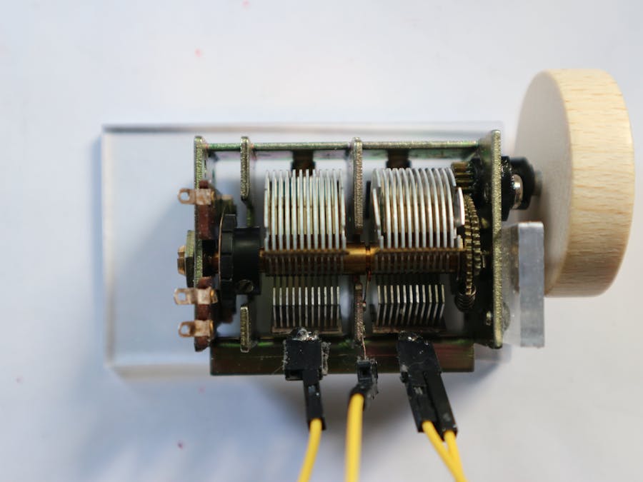
This time, I got some of the old-fashioned variable capacitors [C] which were used to control the frequency of AM receivers. If you add a resistor [R], you can control the time constant given by the product of R and C. (The resistance of the internal pullup-resistor is too low, you really need an external one.)
Similar to the well-known NE555 chip, the capacitor has to be charged and discharged each time the voltage exceeds certain limits. Using the INT0-interrupt (pin d2) things get really easy: Schematics:
/*
  Hardware:
  Vcc -+-[R = 180 kOhm]-+--pin-2
                        |
                        |  ^
                        | /
                     ----/-- variable
                     ---/--- capacitor 720 pF
                       /|
                      / |
  Ground ---------------+-------

  generates a frequency of 35 - 70 kHz
*/
And this is the code:
void setup() {
  Serial.begin(9600);
  Serial.println(__FILE__);
  // rising edge at INT0 generates
  // an interrupt request:
  EICRA = 3;
  EIMSK = 1; // enable INT0 interrupt
  discharge();
}

long t = millis() + 25;
volatile int count;

void loop() {
  delay(25);
  while (millis() < t);
  Serial.println(count);
  count = 0;
  t = t + 25;
}

ISR(INT0_vect) {
  discharge();
  count++;
}

void discharge() {
  pinMode(2, OUTPUT);
  pinMode(2, INPUT);
}
As you can see, whenever the rising voltage at d2 exceeds the limit the discharge function is called and a counter is incremented. The loop-function can print its value on the Serial monitor or the plotter. If you use capacitors with very low values like the one shown in the picture nothing serious will happen. Better don't do it with bigger ones.


Comments