

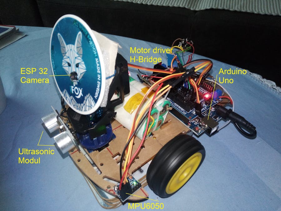
One of the challenges is to get the robot to go in a straight line. With this information, we can instruct our robot to go straight. For this project, we will only need a two (or four-wheeled) robot with appropriate motor drivers, an Arduino Uno board, and an Accelerometer and Gyroscope MPU6050.
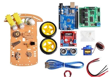
By using a ready chassis it is possible quickly build a working model. If you buy "Robot Smart Car Kit" that includes a chassis, wheels, motors and other mechanical components, to build the robot, we will need only few additional electronics to control the motors and sensors to detect position. The whole electronic design was made based on the Arduino Uno.
At the end we add batteries and charger to power supply the robot and it will be ready for using.
If you try the Smart Robot Car move forward and backward, you may notice that there are some deviations in the direction of the drive. It's very hard to make the car go straight.
The reason is, on the one hand, different terrain has different friction. On the other hand, even the same type of motor may have slight differences in hardware characteristics special by slow drive and down, what may cause the left and right wheels to rotate at different speeds when going "straight". That’s why it deviates from the path slightly.
A solution would be, giving the same PWM value to the motors makes them spin in different speeds. This is usually done by adding "control" to each motor. With use of a 16 bit gyroscope as MPU6050 Gyro sensor or Gyroscope you can detect these 'distortions' and allows you to compensate for it.
Getting the OrientationAccelerometer sensors measure the difference between any linear acceleration in the accelerometer’s reference frame and the earth's gravitational field vector. User-programmable gyroscope has full-scale range of ±250, ±500, ±1000, and ±2000°/sec (dps) and a user-programmable accelerometer full-scale range of ±2g, ±4g, ±8g, and ±16g. Default Gyro Full Scale Range is 250 with a corresponding Sensitivity 131. You need to convert the raw IMU sensor readings into degrees.
Code Description: The first step was to figure out how to extract data from the DMP. There are two ways to extract useful data from the MPU6050. One way is to read the raw sensor data values, as we did during calibration process, and use that data to compute the new orientation. The second method is to pull the data out of the MPU’s onboard Digital Motion Processor (DMP).
Fortunately, it was written and made public a very useful library i2cdevlib. So first we need to include the Wire.h library which is used for the I2C communication and define some variables needed storing the data.
Finally, you don’t need an MPU6050 library to read out the data, as this simple program demonstrates. After initialization, the data of MPU6050 can be read through getRotazion function. The data for each axis is stored in two bytes or registers and we can see the addresses of these registers from the datasheet of the sensor. Here’s the Arduino code getRotazionZ() for reading the raw data about z-axis from the MPU6050 sensor.
Reading raw values is easy, the rest is not. To get the yaw angle using the raw sensor data there are several translations that need to be made. There is a large variation in the values as the sensor starts up, especially in the yaw data. The MPU-6050 needs to be calibrated before it is used for the first time. What we want to do is remove the zero-error. This error can be removed by applying an offset to the raw accelerometer and gyroscope sensor readings. The offset needs to be adjusted until the gyroscope readings are zero (no rotation) and the accelerometer records the acceleration due to gravity pointing directly downwards. Because of the data drift problem of MPU6050, we had better use mean filtering when sampling, and then obtain the z-axis angular velocity value when the car is first placed. The program will make an average of a few hundred readings and get the offsets required to remove zero error.
In many situations, an angular velocity is usually symbolized by the Greek letter omega (ω) and angle as θ. Time is usually symbolized by "t". The Greek letter delta (Δ) indicates the difference between two values. Gyroscopes do not report angles or angular differences, they report the speed at which the device is rotating or the angular velocity ω=Δθ/Δt. It is commonly measured in degrees per second. A yaw rotation is motion about the yaw axis of a rigid body that changes the direction it is pointing to the left or right of its direction of motion.
Before making any calculations you have to translate readings from the body frame to the inertial frame by using the offsets. The offset values “gyroZ0”were calculated during the calibration process and have to store in your program as global variables. In order to get the angle position you have to integrate it over time. The code below shows the time integration being applied to the angular rate information coming from the gyroscope.
Code Description: To bring the body frame of the robot into the inertial frame you have to subtract the offsets from current value ω=(gyroz – gyroz0).
The raw sensor readings need to be converted into degrees prior to applying the integration. This is done by dividing the readings by the sensitivity measurement unit. For a 250deg/s range we have to divide first the raw value by 131.0, according to the datasheet. The Result is the angular velocity ω (°/s). So as the outputs are in degrees, now we need to multiply them with the time to get just angle in degrees Δθ = ω Δt. The time value is captured before each reading iteration using the millis() function.
The yaw rate or yaw velocity of a car is the angular velocity of this rotation, or rate of change of the heading angle. It is commonly measured in degrees per second or radians per second. Nevertheless, once we read the data, we can simply print it on the serial monitor to check whether the values are as expected. In my case, the values I was getting were not exactly as they should be, especially the Z-axis which had a noticeable error of 0.1g. That's why I introduced a hysteresis 0, 05 in the calculation.
Considering that the current position is the sum of each rotation change over time Θ1= θ0 + ω Δt (θ0 -old position and Θ1 new position is), we get the current value of "Yaw". As you can see from the extract of the serial monitor, the value is 0 in the first moment and always shows Start Furnishings. With the information you can now regulate engines so that this value always remains at zero value, i.e. shows start direction.
Proportional controllers may be ubiquitous, but they’re too not perfect. Here you can notice that I correct the output values with some small calculated error values. In case of a direction change we had to make additional correction and correct old variable yaw “(yaw-yawOld)”.
As we can see on the Serial Monitor in the picture up, the values of yaw can be either negative or positive. Depending on the position of the gyro sensor, turning it to the left delivers negative values (y-axis shows in front – by me). The control just has to improve the disorder. So if we want the car to go straight, we need to introduce closed-loop control.
They are using DC motors that have no speed control, so they will always vary compared to each other. You would have to "close the loop" by combining the information of the robot car's position. The control loop tells the robot how fast it should spin each wheel and this will cascade down to the speed control loop that determines how much power to apply. Closed loop control is a fundamental concept in cybernetics. The advantage of the regulation is that the results of the regulation can be fed back and compared with the setpoints and the regulation effect is adjusted based on their errors.
Proportional control refers to an adjustment that is proportional to how much the error is. A P-only controller is intuitive and easy to implement. As the error decreases with each new control effort, so does the next control effort. That in turn slows the rate at which the error decreases until it ceases to change altogether. Unfortunately, that steady-state error is never zero. A P-only controller always leaves the process variable slightly off the setpoint. Basic concept is shown on the following picture.
Code Description: After the yaw data is obtained, the closed-loop feedback control can be achieved through P(ID) algorithm to adjust the wheel speed so as to achieve straight-line walking. Proportional control kp refers to an adjustment of how the amount of error affects the motor. From the listing of subroutine “corrSpeed” we have seen, if error is positive, slow down left motor. Then we need to perform kp proportional control in the PID algorithm on the captured input data. Values between 5 and 30 have been tried. Depending on the position of the gyros, the value of 10-20 has proven best.
The listing below shows how a P control was performed:
Code Description: PID computation must be inside a looping function. To compute corrSpeed() the yaw data is acquired at the first startup, and the data is updated every ten milliseconds. This is task subroutine “driveStraight(int speed)”.
The first part of the function should be determining the time elapsed. In Arduino, the current time can be determined by millis() and the elapsed time is just: currentTime = millis(); and
elapsedTime = currentTime - previousTime;.
Finally I got values for control that integrate both motors into my subroutine „ forward(int is_speed)“ and „back(int is_speed)“.
In main loop I gave only the orders to move. You will see the car move forward and backward at 2s of intervals. In the process of moving forward and backward, the moving route will have no more any deviation and any interference will be compensated.
Auszüge aus dem seriellen Monitor zeigen, wie SpeedL und SpeedR die Yaw-Interferenz kompensieren.
29.06.2024: Because of pin shortage I chose to use the motor driver chip DRV8835. (Although there may be slight differences in the performance of different driver chips, they are generally the same in usage.):
In this guide I want to drive two DC motors using the L298N or DRV8835 H-Bridge. Perhaps everyone is more familiar with L298N. In fact, the use of the two is basically the same.
Something similar is using TB6612 and finally I made adapter based on this model.
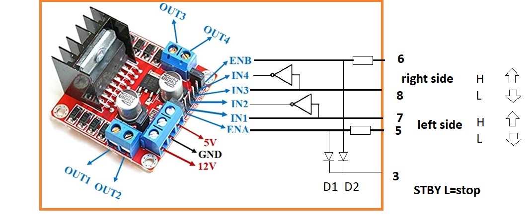
I originally used DRV 8835, but later replaced it with an LN298N, which can lead to confusion. As shown in the circuit diagram, you can use DRV8835 and TB6612 or L298N with adapter. However, if you wish to use an L298N, then please see the table for LN298:
ENA and ENB control the speed of right motor and speed of left motor separately by PWM.IN1 and IN2 are used to control left motor, IN3 and IN4 are used to control right motor. About the principle, please look at the sheet.
First of all, don't forget that "forward" and "backward" are relative. So it depends on the motor connection and if you find the rotational direction of one of the motors is opposite, please change the connecting position of its black and red wires.
Let's see the connection of the motor of the L298N board; I use the Arduino expansion board (Arduino Sensor Shield) pins 5, 6, 7, 8, 3 and on L298N board ENA, ENB, IN1-IN2 and IN3-IN4 to control the car. Definition of the connection ports on L298N board have been marked above. Since the control of both H-Bridges is not identical, I made a small adapter as shown in the picture below.
Adapter does exactly what we need to control motors.
//define DRIVE module IO Pin
#define STBY 3 // STBY < ENR || ENL
#define IN1 8 //Left
#define ENL 6 //PWML
#define IN3 7 //Right
#define ENR 5 //PWMR
And as below subroutine shows command STBY blocks motors. Command IN1 automatically means negative signal for IN2. Command IN3 automatically means negative signal for IN4.
EN stands for Enable pin, which changes motor speed by changing PWM (0~255).
void halt(){
digitalWrite(STBY,LOW);
analogWrite(ENL,0); //set A side speed 0
analogWrite(ENR,0); //set B side speed 0
}
++++++++++++++++++++++++
void forward(int is_speed){
driveStraight(is_speed);
//digitalWrite(ENA,HIGH);
digitalWrite(STBY,HIGH);
// A ... LEFT
digitalWrite(IN1,HIGH); //set IN1 hight level enable A channel CW (automatic IN2 LOW)
analogWrite(ENL,corrSpeedL); //set EN for A RIGHT side speed
// B ... RIGHT
digitalWrite(IN3,HIGH); //set IN3 hight level enable B channel CW (automatisch IN4 LOW)
analogWrite(ENR,corrSpeedR); //set EN for B LEFT side speed
}
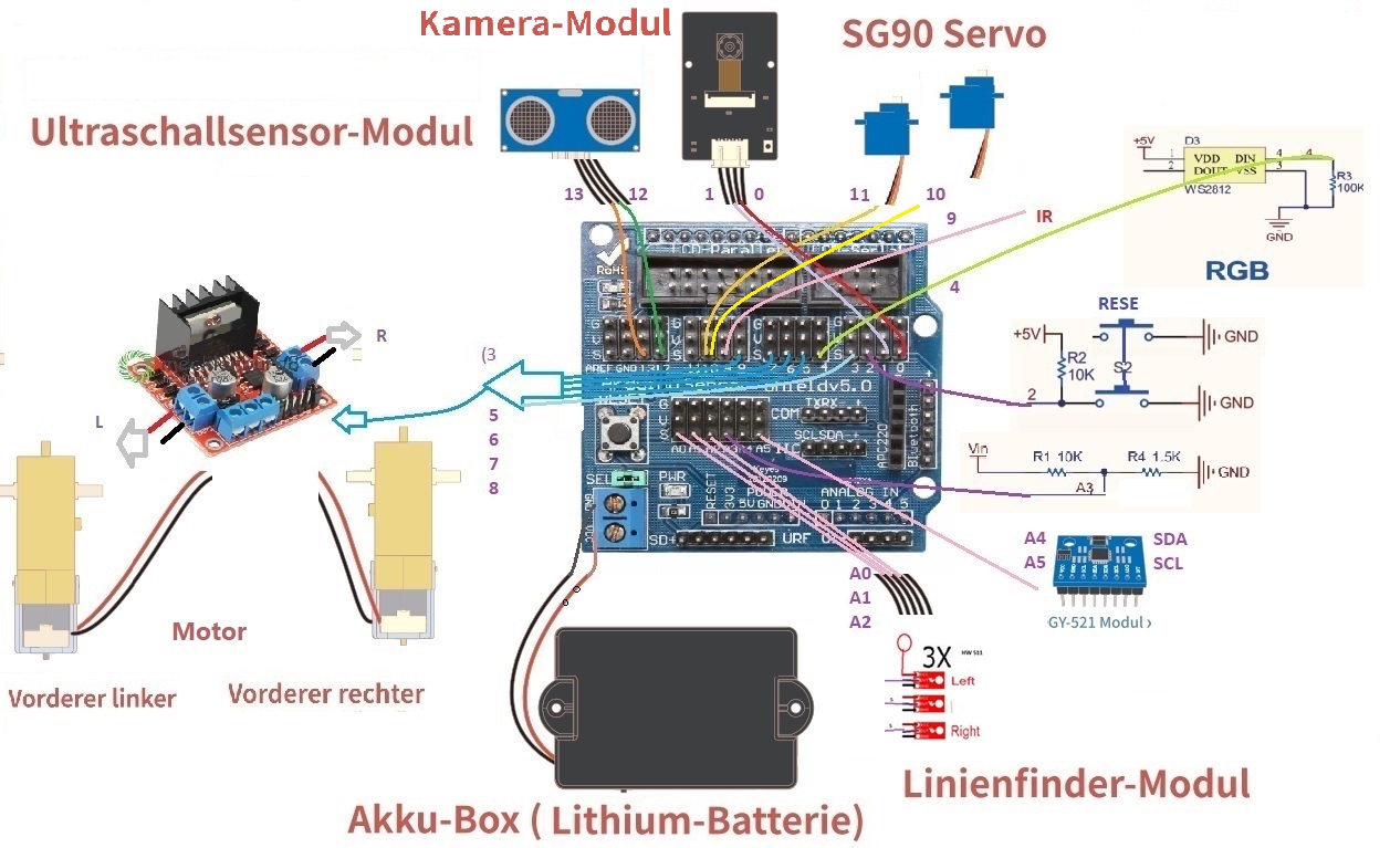
Circuit Diagram
All connections of electronic modules are the following:
MOTOR
With DRV8835 oder L298N with Adapter +5V -GND -12V -
PWMA 5 PWMB 6 BIN_1 7 AIN_1 8 Standby 3
ULTRASONIK MODUL
TRIG_PIN 13 ECHO_PIN 12 VCC - 5V GND – GND
SERVO 10 (left-right) and 11 (down-up) V, GND
ESP32_CAM VCC - 5V/ 3,3V GND TX - RX RX - TX
LINIE Traking
Sensor - R - A0- , M -A1- , L -- A2
V – 5V und GND
build a schasis
All connections of electronic modules are the following:
MOTOR
With TB6612 or DRV8835 and L298N with Adapter +5V -GND -12V -
PWMA 5 PWMB 6 BIN_1 7 AIN_1 8 Standby 3
SERVO 10 (left-right) and 11 (down-up) V, GND
ESP32_CAM VCC - 5V/ 3,3V GND TX - RX RX - TX
LINIE Traking
Sensor - R - A0- , M -A1- , L -- A2
V – 5V und GND
By using a ready chassis it is possible quickly build a working model.


Comments