

Hardware components | ||||||
| × | 1 | ||||
| × | 1 | ||||
Software apps and online services | ||||||
| ||||||
| ||||||
| ||||||
| ||||||
Hand tools and fabrication machines | ||||||
 |
| |||||
| ||||||
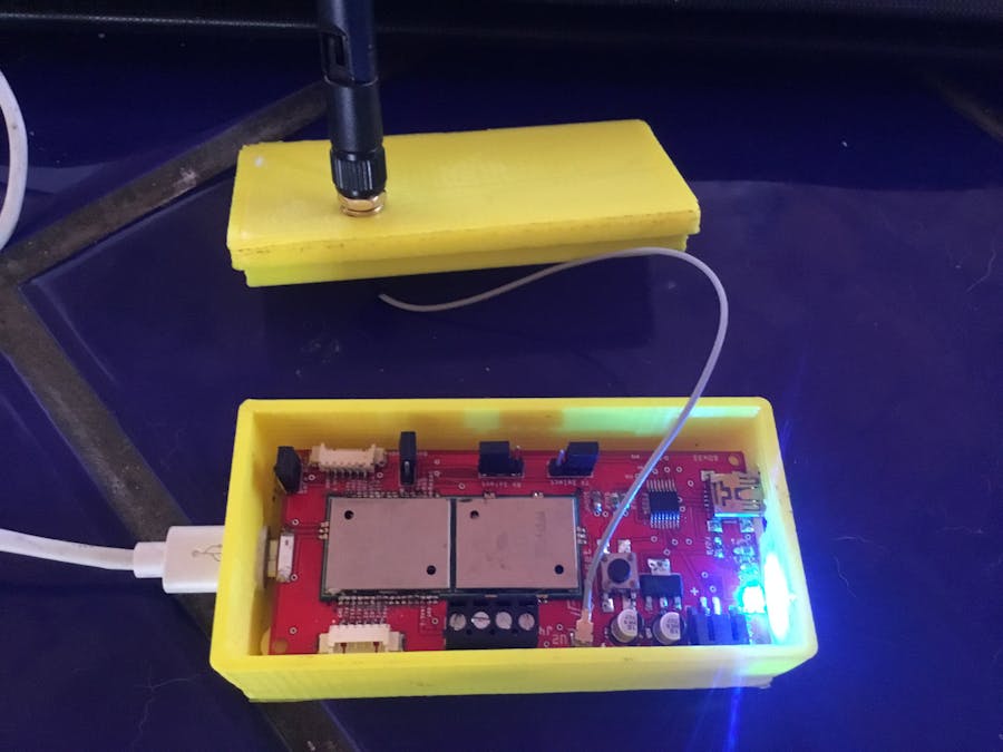
While looking at the functionality of the MAX32625PICO, I realized it would be the perfect IOS driver for a new LoRa/BLE/Wi-Fi board I have been developing. REV1 of the design can be seen in the picture below. I will post the Gerber files and Fritzing files later on so you can make your own sensor array. IoT devices seem to be not going away and makers all over the world are developing solutions and technologies to enable better sensors and monitors. This board will boast multiple inputs including multiple I2C, 15 analog and digital inputs all transmitting data over either BLE (Bluetooth), Wi-Fi, or long-range LoRa wireless.
The project will be in multiple sections:
1. Board Design and Build with Included Files
2. Board Programming and Implementation of Various Sensors
L01 - Programming Links
https://pycom.io/product/l01/
https://docs.pycom.io/chapter/pymakr/installation/vscode.html
https://github.com/pycom/pycom-libraries
https://code.visualstudio.com/docs?start=true
https://git-scm.com/
3. Bill of Materials
Everything on this board is made from readily available materials found in the link below....
4. Enclosure Design and Build with Included files
The Box Was designed with Fusion360 and then converted to a print file using Auto desk Meshmixer..I then exported the file as an STL file for Ultimaker Cura.
The Download for Ultimaker Cure is here
https://ultimaker.com/en/products/ultimaker-cura-software
1. Board Design and Build with Included ilesI designed the board with Fritzing which makes editing and designing pretty easy. A Gerber file is attached for producing your own board.I use PCBWay.com out of China... They are pretty low-cost and fast... 3-day production then shipping... usually from ordering to delivery takes 7 days...
A little tip solder all small SMD parts first... With low temp reflow paste. The larger untis and connectors...
Solder the bottom last.
The first step is figuring out how to program each device. The MAX32625PICO is programmed via a web interface (https://os.mbed.com) and a drag and drop system which is interesting. Once you have the program running, the way you want you can use the Serial output of the MAX32625 to output to the LoRa/BLE/Wi-Fi with some simple wire jumpers.
Step 1: Install Your drivers
https://docs.pycom.io/chapter/gettingstarted/installation/drivers.html
Follow the instructions to install the needed dependencies for programming the Pycom L01
Step 2: Install Visual Studio Code
https://code.visualstudio.com/docs/?dv=win
Step 3: Download the example Code from Github
https://github.com/pycom/pycom-libraries
The Code for this is relatively simple and data coming in on Serial or other Inputs goes out to the LoRa Network.
from network import LoRa
import socket
import binascii
import struct
# Initialize LoRa in LORAWAN mode.
# Please pick the region that matches where you are using the device:
# Asia = LoRa.AS923
# Australia = LoRa.AU915
# Europe = LoRa.EU868
# United States = LoRa.US915
lora = LoRa(mode=LoRa.LORAWAN, region=LoRa.US915)
# create an ABP authentication params
dev_addr = struct.unpack(">l", binascii.unhexlify('00000005'))[0]
nwk_swkey = binascii.unhexlify('2B7E151628AED2A6ABF7158809CF4F3C')
app_swkey = binascii.unhexlify('2B7E151628AED2A6ABF7158809CF4F3C')
# join a network using ABP (Activation By Personalization)
lora.join(activation=LoRa.ABP, auth=(dev_addr, nwk_swkey, app_swkey))
# create a LoRa socket
s = socket.socket(socket.AF_LORA, socket.SOCK_RAW)
# set the LoRaWAN data rate
s.setsockopt(socket.SOL_LORA, socket.SO_DR, 5)
# make the socket non-blocking
s.setblocking(False)
# send some data
s.send(bytes([0x01, 0x02, 0x03]))
# get any data received...
data = s.recv(64)
print(data)
Output to Our LoRa Network
Setting up the MAX32625PICO
/* Pmod Interface Library
*
*/
#include "mbed.h"
#include "SerialInterface.h"
SerialInterface::SerialInterface(I2C *i2c, SPI *spi, DigitalInOut* gpio, AnalogIn* ain): _i2c(i2c), _spi(spi)
{
   _i2c = i2c;  // save pointer to I2C port
   _spi = spi;  // save pointer to SPI port
   _gpio = gpio;  // save pointer to GPIO pins
   _ain = ain;  // save pointer to AIN pins
}
SerialInterface::~SerialInterface()
{
}
/* Analog In
* /a              read all
* /a/[pin]        read from pin
*   Returns 16bit normalized result
*/
void SerialInterface::fnc_ain(char* resp)
{
   switch (_args[0]) {
       case 0:
           sprintf(resp, "[0x%04X,0x%04X,0x%04X,0x%04X,0x%04X,0x%04X,0x%04X,0x%04X]",
           _ain[0].read_u16(), _ain[1].read_u16(), _ain[2].read_u16(), _ain[3].read_u16(),
           _ain[4].read_u16(), _ain[5].read_u16(), _ain[6].read_u16(), _ain[7].read_u16() );
           break;
       case 1:
           sprintf(resp, "[0x%04X]", _ain[_args[1]].read_u16());
           break;
       default:
           sprintf(resp, "[-1]");
           break;
   }
}
/* Digital I/O
* /d              read all
* /d/[pin]        read from pin
* /d/[pin]/[cfg]  write configuration to pin
* [pin] = number (from 0 to 7) of the pin to access
* [cfg] = pin configuration:
*     0 - output low
*     1 - output high
*     2 - input pull down
*     3 - input pull up
*     4 - input pull none
*/
void SerialInterface::fnc_dio(char* resp)
{
   int bdat;
   int bcnt;
   switch (_args[0]) {
       case 0:
           sprintf(resp, "[");
           resp +=1;
           for (bcnt = 0; bcnt < 8 ; bcnt++) {
               bdat = _gpio[bcnt].read();
               sprintf(resp, "%d,", bdat);
               resp +=2;
           }
           sprintf((resp-1), "]");
           break;
       case 1:
           if (_args[1] > 7) {
               sprintf(resp, "[-1]");
           } else {
               sprintf(resp,"[%d]", _gpio[_args[1]].read());
           }
           break;
       case 2:
           if (_args[1] > 7) {
               sprintf(resp, "[-1]");
           } else {
               if (_args[2] < 2) {
                   _gpio[_args[1]].write(_args[2]);
                   _gpio[_args[1]].output();
               } else {
                   if (_args[2] == 2) {
                       _gpio[_args[1]].mode(PullDown);
                   } else if (_args[2] == 3) {
                       _gpio[_args[1]].mode(PullUp);
                   } else {
                       _gpio[_args[1]].mode(PullNone);
                   }
                   _gpio[_args[1]].input();
               }
               sprintf(resp,"[%d]", _args[2]);
           }
           break;
       default:
           sprintf(resp, "[-1]");
           break;
   }
}
/* I2C
* /i/[even]/[data]...       write
* /i/[odd]/[cnt]/[data]...  read
* [even] = even I2C address used for writes
* [odd]  = odd I2C address used for reads
* [data] = data to be writen, if data is included with a read, the data
*     will be written prior to the read to set the register address
* [cnt]  = number of bytes to read
* returns data read in JSON array
*/
void SerialInterface::fnc_i2c(char* resp)
{
   int dcnt=0;
   if (_args[IA_CNT] < 2) {
       sprintf(resp, "[-1]");
   } else {
       if (_args[IA_ADD] & 1) {
           sprintf(resp, "[");
           resp +=1;
           if (_args[IA_CNT] > 2) {
               for (dcnt = 0; dcnt < (_args[IA_CNT] -2) ; dcnt++) {
                   _dbuf[dcnt] = _args[(dcnt +3)];
               }
               if ((*_i2c).write(_args[IA_ADD], _dbuf, dcnt, true) != 0) {
                   sprintf(resp, "-1,");
                   resp +=3;
               }
           }
           if ((*_i2c).read(_args[IA_ADD], _dbuf, _args[IA_DATA])!=0) {
               sprintf(resp, "-1]");
           } else {
               for (dcnt = 0; dcnt < _args[IA_DATA]; dcnt++) {
                   sprintf(resp,"0x%02X,", _dbuf[dcnt]);
                   resp +=5;
               }
               sprintf((resp-1), "]");
           }
       } else {
           for (dcnt = 0; dcnt < (_args[IA_CNT] -1) ; dcnt++) {
               _dbuf[dcnt] = _args[(dcnt +2)];
           }
           if ((*_i2c).write(_args[IA_ADD], _dbuf, dcnt) == 0) {
               sprintf(resp,"[%d]", dcnt);
           } else {
               sprintf(resp, "[-1]");
           }
       }
   }
}
/* SPI
* /s/[cfg]/[data]...      read+write
* [cfg] = SPI configuration specifies gpio to use for chip
*   select and other SPI parameters:
*   0x[Byte3][Byte2][Byte1][Byte0]
*     Byte3 = SCK frequency in MHz (0 = no change)
*     Byte2 = Format:
*       0 = no change
*       1 = Mode 1
*       2 = Mode 2
*       3 = Mode 3
*       4 = Mode 0
*     Byte1 = CS polarity 1 = active high, 0 = active low
*     Byte0 = GPIO to use for CS (0-7)
*       0 = P5_3
*       1 = P5_4
*       2 = P5_5
*       3 = P5_6
*       4 = P3_0
*       5 = P3_1
*       6 = P3_2
*       7 = P3_3
* [data] = data to be writen
*   this shifts out each data byte provided and
*   returns each byte read in a JSON array
*/
void SerialInterface::fnc_spi(char* resp)
{
   int dcnt=1;
   int dataIn;
   spiConfig_t spiCfg;
   if (_args[0] < 1) {
       sprintf(resp, "[-1]");
   } else {
       spiCfg.merged = _args[1];
       if (spiCfg.freq) {
           (*_spi).frequency(spiCfg.freq * 1000000);
       }
       if (spiCfg.format) {
           (*_spi).format(8, (spiCfg.format & 3));
       }
       if (_args[0] > 1) {
           sprintf(resp, "[");
           resp++;
           _gpio[spiCfg.csPin] = (spiCfg.csPol);
           while(dcnt < _args[0]) {
               dcnt++;
               dataIn = (*_spi).write(_args[dcnt]);
               sprintf(resp, "0x%02X,", dataIn);
               resp += 5;
           }
           _gpio[spiCfg.csPin] = !(spiCfg.csPol);
           sprintf((resp-1), "]");
       }
   }
}
void SerialInterface::call(char* input, char* output)
{
   char cmd;
   _args[0] = 0;
   if (*input == '/') {
       input++;
       cmd = *input;
       input = strchr(input, '/');
       while (*input == '/') {
           input++;
           _args[(_args[0]+1)] = strtol(input, &input, 0);
           if (input) {
               _args[0]++;
           }
       }
       switch (cmd) {
           case 'a':
           case 'A':
               fnc_ain(output);
               break;
           case 'd':
           case 'D':
               fnc_dio(output);
               break;
           case 'i':
           case 'I':
               fnc_i2c(output);
               break;
           case 's':
           case 'S':
               fnc_spi(output);
               break;
           default:
               sprintf(output, "!commands: ain dio i2c spi");
               break;
       }
   } else {
       sprintf(output, "!format:  /cmd/arg1/arg2...");
   }
}
Compile and Drag the Compiled code to the Max Folder..
It may toss an error but don't worry unplug and plug it back into power the code will run.
To power your device, you have 3 options:
Option 1: The MAX32625PICO side also used for programming the PICO
Option 2: LoRa L01 side also used for programming the L01
Option 3: Battery power for deployment
I have provided a link as a shopping cart and listed the parts and pieces here...


Comments