


Hardware components | ||||||
 |
| × | 1 | |||
| × | 1 | ||||
Software apps and online services | ||||||
 |
| |||||
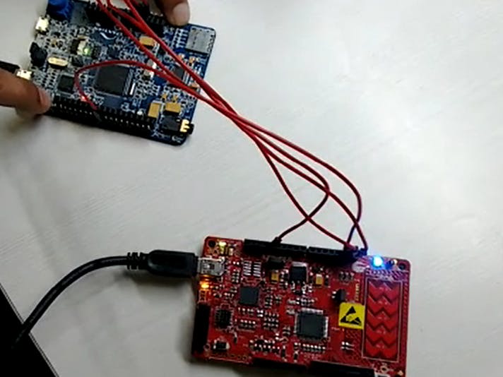
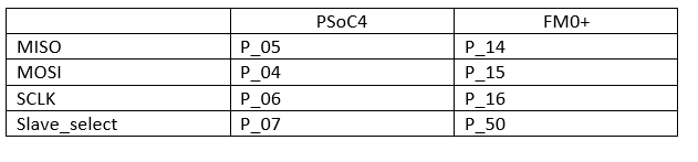
FM0 schematic includes the one MFS component in CSIO mode as an SPI Master.
And select a firmware-controlled slave, as well as an input GPIO to collect user input. PSoC4 contains one SCB component configured as SPI slave, and three output GPIO to control 3 LEDs (red, green, and blue).


Comments