


Hardware components | ||||||
 |
| × | 1 | |||
| × | 1 | ||||
| × | 1 | ||||
Software apps and online services | ||||||
| ||||||
| ||||||
Have you ever wondered what actually moves an RC plane’s ailerons or a 3D-printed robotic hand? So many cool moving projects you see on YouTube are secretly powered by cheap hobby servo motors.
In this protip, we're going make two common servos spin and sweep using the PSOC™ 6 Wi-Fi BT Prototyping Kit and a few lines of MicroPython.
By the way:
The PSOC™ 6 Wi-Fi BT Prototyping Kit is a development board that features the PSOC™ 6 (Programmable System-on-Chip) microcontroller, a powerful and flexible chip that can be used for a wide range of applications. Here are some projects we've made using this chip: The Alligator Bicep Trainer, the Oktoberfest Smart Beer Stein or the Self-Balancing Robot.Pinout
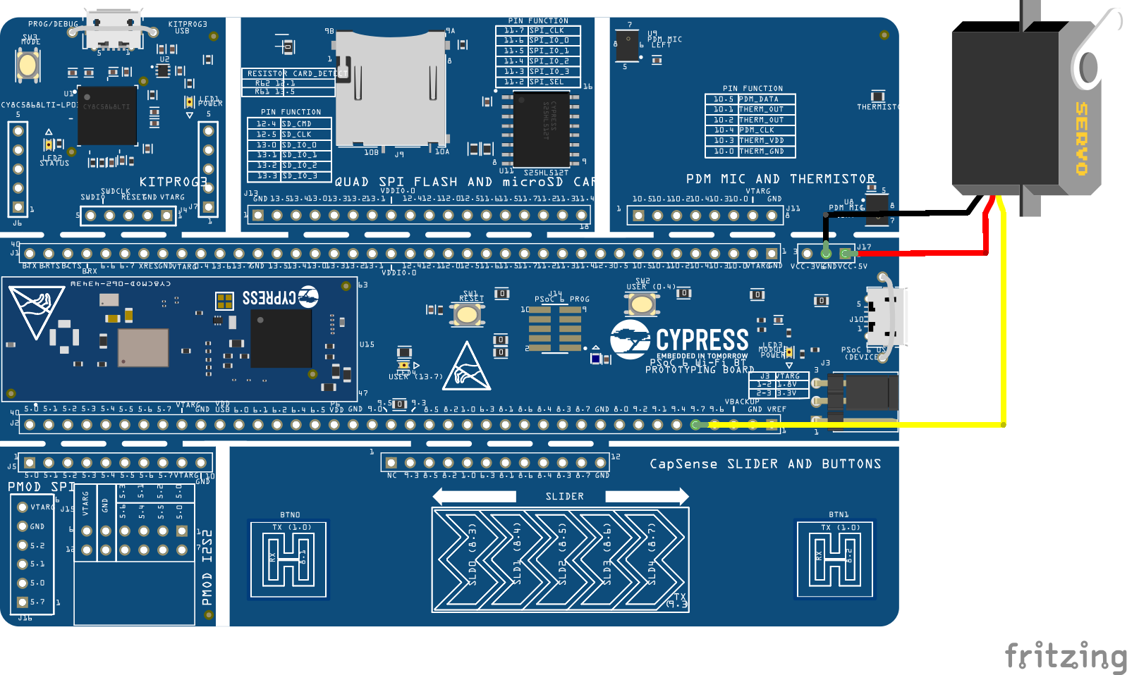
The first step is connecting your board to your servo motor and PC. RC-Servo motors generally have three outputs:
- The darkest wire connects to GND.
- The one in the middle connects to VCC (check your datasheet for the required voltage).
- The lightest connects to any pin that supports PWM communication (we'll get into that later). In this case we chose pin 9.7, but you can use whichever one you like, you'll just have to change the code accordingly.
To connect to your PC, plug a micro-USB into the upper left connector (KitProg3 USB connector).
Setting up MicroPythonIf this is your first time using MicroPython on the PSOC™ 6 Prototyping Kit, you'll need to flash the software onto your microcontroller first. We've already prepared a protip and an article explaining how to use MicroPython on PSOC™ 6.
Servo Motor communication with PWMWhat is PWM and how does PWM communication work?
PWM stands for "Pulse Width Modulation" and is a way for the microcontroller to communicate with servo motors and other components. Every motor has a frequency as a set parameter (check the datasheet of your respective motor accordingly), at which the microcontroller sends a pulse to the motor, so once every period T = 1/f.
Input is received by how long the signal is set to high (pulse width) during that period T, often within a motor specific range. Modulating (changing) the pulse width will change your motor output.
Different servos have different ways of interpreting this data, today we'll look at two examples using the SG90 (positional servo) and MG995 (continuous servo).
Connecting Board and using Thonny IDE
We'll be using the Thonny IDE to run our code. To connect to your microcontroller and use MicroPython, create a new file, and press Tools > Options > Interpreter. There, set the interpreter to MicroPython (generic) and the port to KitProg3 USB-UART @ your COM port (COM4 in this case).
Setting Pin and PWM
Firstly, you'll need to import the PWM library from the machine library. Then, set a pin to a PWM pin by declaring it (pin 9.7 in this example), setting the PWM frequency, and initializing the pulse width. The starting_pw will be defined later on depending on which motor we use.
from machine import PWM

pwm_pin = PWM('P9_7', freq=50, duty_ns=starting_pw)  # PWM is initialized for the given pin with respective frequency & duty cycle given in nanoseconds.
Tip: Setting the Pulse Width
There are many different ways to set the pulse width, eg. using the two functions defined in the PWM library. The first one, as shown above, sets the pulse width in nanoseconds, using the duty_ns() function. The second one sets it by sending an unsigned 16 bit integer using the duty_u16() function. This represents the duty cycle (ratio of current pulse width to period), with values ranging from 0% of the period (0 bits) to 100% of the period T (2^16 = 65, 536 bits).
Check out more on PWM control with the PSOC™ 6 Wi-Fi BT Prototyping Kit here!Example 1: Positional Motor
General
Positional motors take the pulse width as an input and map it to a certain angle, as shown in the following graph:
Parameters
Our motor has these parameters:
- angle_max = 180°
- angle_min = 0°
- frequency = 50 Hz ≙ period = 20 ms
- pw_min = 0.5 ms: our minimum pulse width is 0.5 ms or 500000 ns, which will set our motor to our minimum angle.
pw_max = 2.5 ms: our maximum pulse width is 2.5 ms or 2500000 ns, which will set our motor to our maximum angle.
Code
Our goal is to create a function called set_motor_to_angle() that takes our desired angle as an input, translates it into the pulse width, and sends it to the motor. In order to do that, we'll define an auxiliary function angle_to_ns() that does all the pulse width calculations.
# Import libraries needed for pin communication and time measurement
from machine import PWM
import time

# Set parameters - motor specific!
pw_min = 500000 #ns
pw_max = 2500000 #ns
angle_min = 0 #degrees
angle_max = 180 #degrees
frequency = 50 #Hz

# Initialize PWM at pin 9.7 and set the initial pulse width to pw_min
pos_servo = PWM('P9_7', freq=frequency, duty_ns=pw_min)

'''Auxiliary function, maps angle to pulse width'''
def angle_to_ns(angle):
    # Check if angle is in range
    if(angle_min <= angle and angle <= angle_max):
        # In range -> Calculate pulse width
        angle_percentage = (angle - angle_min)/(angle_max - angle_min)
        ns_percentage = angle_percentage
        ns = ns_percentage*(pw_max - pw_min) + pw_min
        # Print ns to help with troubleshooting later on
        print(ns, "ns")
        return ns
    else:
        # Not in range -> Return error
        print("Error: Angle not in range!")
        return False

'''Takes angle, calculates pulse width and sends signal to servo'''
def set_motor_to_angle(angle):
    # Gets the pulse width from auxiliary function
    ns = angle_to_ns(angle)
    if (ns is False): return
    #Convert float to int
    ns = int(ns)
    # Check if the conversion has pushed the pulse width out of bounds
    #-> adjust accordingly
    if(ns > pw_max):
        ns = pw_max
    elif (ns < pw_min):
        ns = pw_min
    # Send signal to motor
    pos_servo.duty_ns(ns)

''' Test function, uncomment to test
while (True):
    set_motor_to_angle(200) #should return error message
    time.sleep(0.5)
    set_motor_to_angle(180) #should set motor angle to 180
    time.sleep(0.5)
    set_motor_to_angle(10) #should set motor angle to 10
    time.sleep(0.5)
'''General
Continuous motors map the pulse width to the speed of the motor, as shown in the following graph:
Parameters
The motor used here has the parameters:
- pw_min = 1 ms: means rotating at full speed in a clockwise direction (positive speed).
- pw_max = 2 ms: means rotating at full speed in an anti-clockwise direction (negative speed).
- gradient = -777846 ns/Hz: describes the ratio: pulse width/rotational speed. We're going to use this in our function to map rotational speed to pulse width. You can either get this number from your datasheet or easily calculate it yourself.
- pw_stationary = (pw_max-pw_min)/2 + pw_min = 1.5 ms: this is the pulse width value when the motor speed is at 0 Hz (when it's stationary). We need this (or any other point on the graph), because a linear function needs both a gradient and a point to be fully defined.
Calculating the gradient
Our first assumption is that our speed to pulse width ratio is approximately linear, this simplifies our calculations significantly. To reconstruct the graph, we'll need to measure a few data points and use them calculate the gradient. The actual function will use the gradient(a) and the one point on the graph(b) in an a*x + b format.
Tip: Measuring rotational speed
This can be done by setting the motor to a certain pulse width and filming it with your phone camera. Put it next to something to help track its movement and let it rotate 10-20 times to minimise errors and increase accuracy. Then replay the footage frame by frame to see how long all those turns took and calculate: (amount of turns)/(time) to get the rotations per second.
Code
Our goal is to create a function called set_motor_to_speed() that takes our desired speed as an input, translates it into the pulse width, and sends it to the motor. In order to do that, we'll define an auxiliary function speed_to_ns() that does all the pulse width calculations.
# import libraries needed for pin communication
from machine import PWM

# Set parameters
pw_min = 1000000 #ns
pw_max = 2000000 #ns
pw_stationary = (pw_max-pw_min)/2 + pw_min #ns
gradient = -777846 #ns/Hz

'''Example: gradient calculations using MG995
1. pw_min -> 18 turns,28sec -> +0.6428 turns per second! (clockwise)
2. 1250000 -> 14 turns, 28 sec -> +0.5
3. 1750000 ->14 turns, 26 sec -> -0.5384 turns per second! (anticlockwise)
4. pw_max -> 16 turns, 22sec -> -0.7272 turns per second!
smallest max speed: min(0.6428, 0.7272) = 0.6428
gradient: -500000ns/Hz / 0.6428 = -500000/0.6428 ns/Hz = -777846ns/Hz (negative gradient, see graph)
'''

# Initialize PWM at pin 9.7 and set the initial pulse width to pw_stationary
#-> motor is stationary
cont_servo = PWM('P9_7', freq = 50, duty_ns = int(pw_stationary)) # PWM is initialized for the given pin with respective frequency & duty cycle given as raw value.

'''Maps speed (in Hertz) to pulse width (in ns).
Clockwise is positive, anti clockwise is negative'''
def speed_to_ns(speed):
    ns = gradient*speed + pw_stationary
    return ns

'''Takes speed, calculates pulse width and sends signal to servo'''
def set_motor_to_speed(speed):
    ns = speed_to_ns(speed)
    ns = int(ns)
    # Print ns to help with troubleshooting later on
    print(ns, "ns")
    # Check if in range
    if(pw_min <= ns and ns <= pw_max):
        cont_servo.duty_ns(ns)
    else:
        # Calculate the max speed (can use pw_min or max)
        max_speed = (pw_min - pw_stationary)/gradient # y = ax + b -> x = (y-b)/a
        print("Error: Speed not in range!")
print("Max Speed is:", -max_speed)Thanks for reading! Now you know how to control two different types of servo motors using our PSOC™ 6 board and MicroPython. Feel free to like, comment and share the projects you create with this guide!

Comments