

Hardware components | ||||||
 |
| × | 1 | |||
 |
| × | 1 | |||
 |
| × | 1 | |||
 |
| × | 1 | |||
| × | 1 | ||||
| × | 1 | ||||
| × | 1 | ||||
Software apps and online services | ||||||
 |
| |||||
Hand tools and fabrication machines | ||||||
 |
| |||||
 |
| |||||
Normally red buttons mean catastrophe, from nuclear blast to emergency evacuation to opening quantum tunnels, etc. To change this bloody and fearful association planted deep in our subconscious minds, how about this time the red button is just a way to deploy a cute gift to celebrate every day until Christmas Eve?
With the help of Arduino IDE, XMC 1100 Boot Kit and some shields, you can achieve that and build an automated advent calendar that's impressive!
Not only will you impress everyone with your creativity, but you'll also have a (non-nuclear) blast building and using it. So why settle for a conventional advent calendar when you can design your own? Read on and find out how this advanced calendar was built!
1 Idea and DesignThe idea was to make it not like every year's advent calendar. The gifts will fall off onto your hand or on the floor if you have slow reflexes. You just have to push a button and an external RTC module will see which date you're on and drop a gift accordingly, if it hasn't already dropped one (don't try to be cheeky here ;) ).
These gifts hang on a dry 1, 75mm PLA 3D filament which will get retracted day after day using an XMC 1100 Bootkit and an IFX9201 Stepper Motor Control Shield controlling a Stepper Motor with an Extruder mechanic attached to it. This 3D filament goes through holes of custom-made 3D printed parts, Filament Holder and Tube Holder, which you can find in the attachments section.
The calendar's design is a custom Christmas tree made out of a 3mm thick display cardboard by wirmachendruck.de, whose design file can also be found in the attachment section.
This cardboard was later laser-cut to push the filament- and tube holders through the back and glue them on the back of the display cardboard:
Filament holders have a 1,8-2mm hole where the PLA filament goes through and there are also some Tube holders meant for a 4mm Teflon tube where the filament also goes inside when having to curl to shift rows on the Christmas tree.
Finally, the whole Christmas tree is pushed through a big custom 3D-printed Base (or stand) where all the cables are managed and the Shield- and XMC board are screwed on. This base also has a hole dedicated to slide the filament which gets retracted in order to contain and hide it:
NOTE: You may have noticed that some words are in bold. These words are bold because those are all the components used in order to make this project happen.2 The "suicide"- circuit
To make the whole setup last on a battery we decided to put the whole setup in a "no power" mode. This means the system gets connected to the main battery by the push of a button. From this moment on the controller uses a smart high-side switch to keep itself alive. After the job of retracting the filament is done the controller disconnects itself from the battery. Only the RTC module is continuously active, powered by a coin cell.
The flow of operation can be described as follows:
Now, a quick "Suicide-Switch" Demonstration:
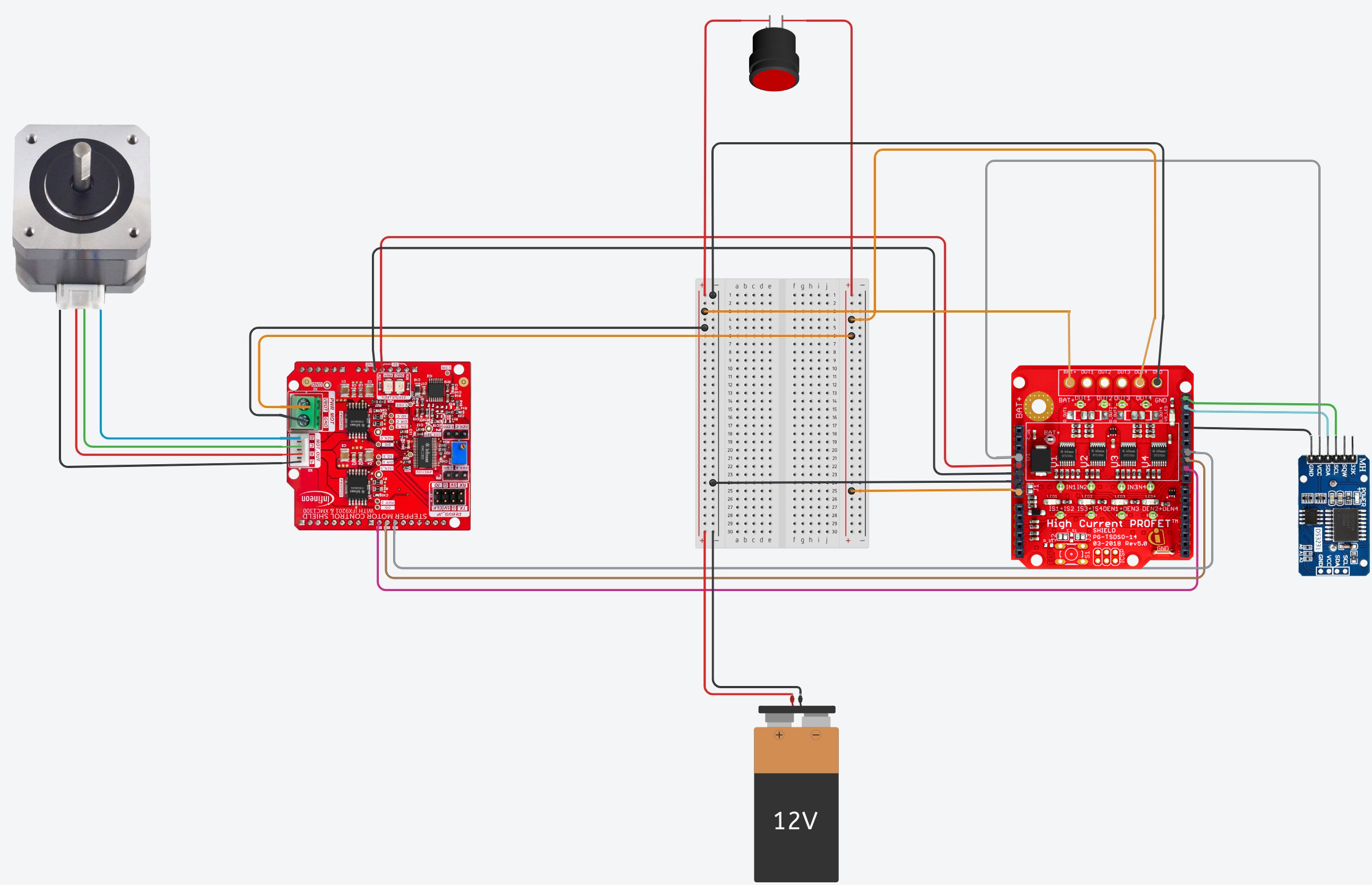
This is the schematic for the whole project:
NOTE: The High Switch Shield (HSS) is mounted on top of the XMC1100 Boot Kit, so no need to draw the XMC Boot Kit in the Pic
NOTE: The Stepper Motor Shield only needs the following pins: 5V, GND, DIR(9), STP(10) and DIS(11).
I can see you squinting your eyes to see which cable is going from where to where, having trouble? Have a look at this table instead:
To mount the boards on the base they were simply placed and aligned with their designated holes and screwed on with M2,5 screws. As for the motor, the Extruder from the Hardware Components section comes with Its screws you simply insert the motor from inside the base and screw the extruder from the top.
HINT: Take a look at the second photo in the previous section: Final look (back)4 Code & Software
If you're not familiar with Infineon's XMC µC in combination with Arduino IDE, go check out this article. This should provide you with the basic knowledge you need for this project.
The main libraries used for this project were:
- Stepper Motor Shield: to control the Extruder
- DS3231 RTCLib: to read Date and Time
- XMCEEPROMLib (in the attachments section): to save the last known date in the non-volatile memory of the XMC
NOTE: There is a well written article about this library, check it out!
- High Side Switch (HSS): to Power Off the XMC
The flow of the software part is simple:
- The push button is pressed once => a GPIO pin goes high to close the high side switch shield with BTS7002-1EPP and the circuit so that current flows even though the button is not pushed down
NOTE: switch_no 4 was used, because this pin is not occupied neither by the Stepper Motor shield or by the RTC Module
- Check the date from the external RTC module that has a coin cell battery to keep track of time when powered off
- If date is not the same date as before (new day, new gift) then Stepper Motor extrudes XXX number of steps and the hanging gift falls
NOTE: The number of steps needed were calibrated using the MotorCalibration program from the attachments section.
- If for some reason the button had not been pressed for one or more consecutive days then if pressed accumulate the steps needed until the present date is reached and extrude XXX+YYY number of steps
- Gift disposed? Power off!
This program is realized by the Arduino file in the code section below and the details about some functions or lines can be found in the line comments of that file.
5 Merry Christmas!So this is it, enjoy your holiday and count the days till Christmas Eve with this amazing advent calendar! Just don't forget to push the red button every now and then to open your fabulous gifts.
Stay safe, stay warm, and Merry Christmas from your Infineon Team!
Christmas Tree Design with Cuts
Deco from: https://de.freepik.com/vektoren-kostenlos/packung-mit-schoenen-dekorativen-weihnachtsbordueren_1443492.htm#&position=0&from_view=search&track=ais&uuid=88ffe556-6cf4-409e-807c-30b433e31ea5


Comments