

Hardware components | ||||||
_ztBMuBhMHo.jpg?auto=compress%2Cformat&w=48&h=48&fit=fill&bg=ffffff) |
| × | 1 | |||
 |
| × | 1 | |||
| × | 1 | ||||
| × | 1 | ||||
| × | 1 | ||||
| × | 1 | ||||
| × | 3 | ||||
| × | 6 | ||||
Software apps and online services | ||||||
 |
| |||||
Hand tools and fabrication machines | ||||||
 |
| |||||
 |
| |||||
Lab bench power supplies are either expensive or they have a weak power output range. You might face this problem, when you want to test an application, that exceeds the typical 5 Amps limit, like (brushless) motor controllers. But often it’s enough, to take a high power constant voltage source like LiPo or Pb batteries and just limit the current.
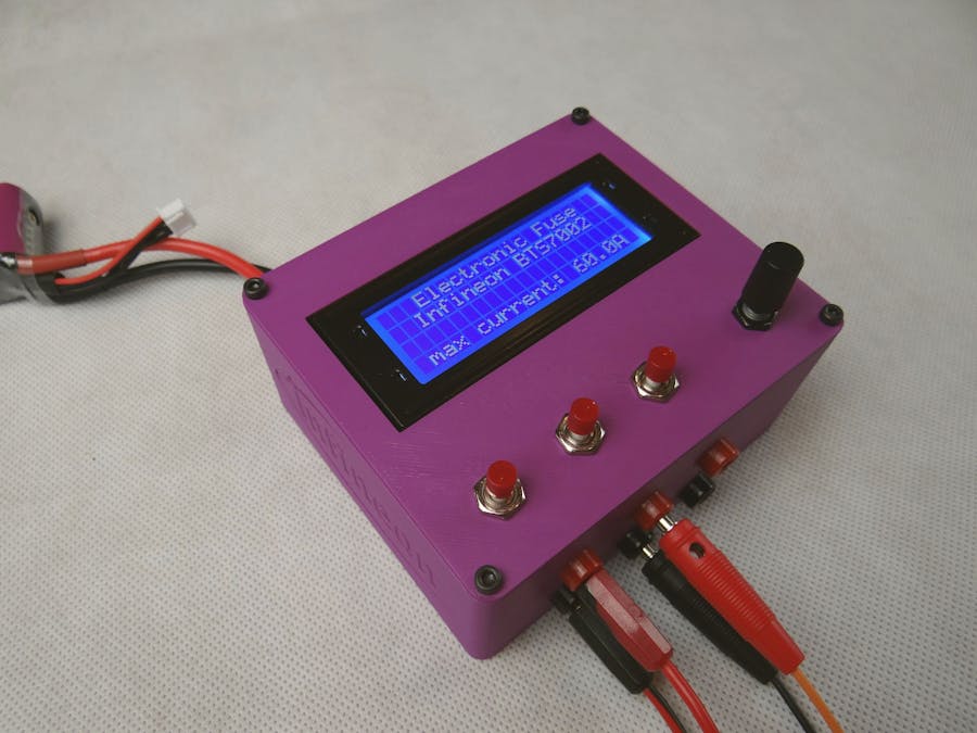
In this article we will show, how to build such an Electronic Fuse, which can switch off at a certain threshold current and shows all voltage/current values on an LCD display like on a power meter.
Key component is the Infineon PROFET™ +2 12V Arduino shield featuring BTS7002-1EPP high-side switches, stacked on an Arduino UNO. The shield is equipped with four high-side switches (HSS), which are able to precisely measure the output current while offering self-protection and diagnostic functions. This allows the Arduino to constantly monitor the output current and to switch off the PROFET™ when the threshold current, which was defined on the LCD display, is exceeded. In case of faulty conditions, the PROFET™ even switches off autonomously.
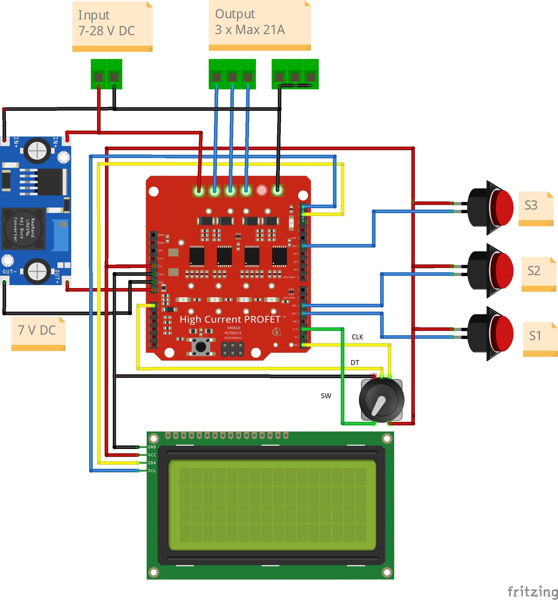
Overview- Input voltage: 7-28V
- Max. input current: 60A
- Max. output current: 3 x 21A
On the startup screen, you can configure the maximum input current. This might be useful, if you want to protect your battery from delivering too much current, so the summarized output current on all three outputs will not exceed this limit.
When you press the rotary encoder, you will come to the main screen. The top line shows the supply voltage (Batt) and the time delay (td). This specifies the delay between 0 and 950 milliseconds until the fuse switches off after an output exceeded its threshold. If td is 0ms, there will still be a delay of about 20 milliseconds due to the processing time of the microcontroller.
The three lines below show the statuses of the high-side-switches, their actual current and their current thresholds (th). The thresholds can be changed as well between 0.2A and 21A with the rotary encoder. Statuses are:
- "ON": high-side switch is turned on, output is active.
- "OFF": high-side switch is turned off, output is inactive
- "OVC": overcurrent, threshold was exceeded and high-side switch has turned off. Press the red button in order to reset status and print "OFF" again.
All values (time delay and thresholds) will be stored to the Arduino EEPROM, so your changes will be restored the next time you power up the E-Fuse.
Although the BTS7002-1EPP Arduino shield is equipped with four high-side switches, we will only use three of them in this application, limited by the GPIOs of the Arduino.
Step 1: 3D-printing of housingBefore getting started with soldering, you may want to switch on your 3D-printer in order to print the housing while you are doing the electronics. The STL-files are provided below. There are only two pieces to print (the bottom part and the top part), 30% infill and without using support material. Standard PLA with 0.2mm layer height is sufficient. Of course you can use any other housing as well, if no 3D-printer is available.
If you will mostly use inductive loads, I would recommend also to solder the Flyback-Diodes. You can use the SK54A-LTP (5A / 40V in SMA package).
Please refer to the schematics in the board manual for more detailed information.
As the board switching current is rated for up to 21 Amps, don’t economize with the power cables. We recommend 2, 5mm² - 3,0mm². If available, use proper crimping tools. When soldering the XT60 connector, plug in the female connector so the metal contacts will stay in place if the surrounding plastic melts. In order to avoid short circuits, use heat shrink on all contacts.
As the Arduino has only an onboard voltage regulator for voltages up to 12V and low currents (otherwise it gets too hot), we would recommend to use a Step-down converter module (e.g. with LM2596). The Arduino will then be powered as well by your main input voltage and you don’t need the USB cable. To calibrate the step-down converter, take a voltage supply with more than 10V, attach a Multimeter to the output of the Step-down converter and turn the small screw until you reach 7, 0V (leave disconnected of the Arduino first!).
However be aware, that if your supply voltage breaks down, the Arduino will shut down as well.
When finished, use M2, 5 screws to attach the XT60 connector to the housing and M3x5 to screw the Arduino in the housing. Next you can stack the shield onto the Arduino and proceed with the wiring of the LCD-display, the three red on/off buttons and the rotary encoder knob. Refer to the schematics below for pinout information.
Download the Arduino sketch with the 'Electronic Fuse Code' below. You will also need to install the following libraries inside the Arduino IDE (Tools -> Manage Libraries…):
- LiquidCrystal I2C by Frank de Brabander (V1.1.2)
- High-Side-Switch by Infineon (V0.1.3)
Plug your Arduino via USB, select the correct Port (Tools -> Port) and hit the upload button.
Step 5: Tuning for expertsKey value for a good Electronic Fuse is its delay until it switches off after an overcurrent event. However this application is aimed at hobbyists and makers, who want to avoid damage to their circuit. In this application, the minimum delay that can be achieved by default (when td = 0ms) is about 10 ms. One reason therefore is the rolling average measurement of the current. If you would decrease the AMOUNT_MEASUREMENTS, your response gets faster. Therefore it might happen that you get a wrong detection because of the increased measurement ripple. Second reason for this huge delay are the LCD Vbatt and current updates every second, because the lcd.print() command takes several milliseconds as well.


Comments