

Hardware components | ||||||
 |
| × | 1 | |||
_ztBMuBhMHo.jpg?auto=compress%2Cformat&w=48&h=48&fit=fill&bg=ffffff) |
| × | 1 | |||
Software apps and online services | ||||||
 |
| |||||
In this protip, we'll go over how to use the BTN8982TA Arduino shield and go into the shield's functionalities, so you could add it to your arsenal on your road to building your project!
What is the shield all about?The DC motor control shield from Infineon technologies is one of the first high current motor control boards being compatible with Arduino as well as with Infineon’s XMC1100 Boot Kit. The DC motor control shield is capable to drive two uni-directional DC motors (half-bridge configuration) or one bi-directional DC motor (H-Bridge configuration). The implemented integrated BTN8982TA NovalithIC™ half bridges can be controlled by a PWM via the IN Pin. Interfacing to a microcontroller is made easy by the integrated driver IC which features logic level inputs, diagnosis with current sense, slew rate adjustment, dead time generation and protection against overtemperature, undervoltage, overcurrent and short circuit.
- Unidirectional single motor control: controlling a single dc motor in a single direction and being able to power it on 256 different levels using PWM.
- Unidirectional dual motor control: controlling two DC motors in a single direction each and being able to power both individually on 256 different levels using PWM.
- Bidirectional single motor control: controlling a single DC motor in two directions of motion and being able to power the motor on a scale of 255 levels in each direction using PWM.
In the Arduino IDE copy the following code snippet:
const int IS_1 = A0;
const int IN_1 = 3;
const int INH_1 = 12;

const int IS_2 = A1;
const int IN_2 = 11;
const int INH_2 = 13;

void setup() {
  pinMode(IS_1, INPUT);
  pinMode(IN_1, OUTPUT);
  pinMode(INH_1, OUTPUT);
  pinMode(IS_2, INPUT);
  pinMode(IN_2, OUTPUT);
  pinMode(INH_2, OUTPUT);

  analogWrite(IN_1, 0);
  digitalWrite(INH_1, HIGH);
  analogWrite(IN_2, 0);
  digitalWrite(INH_2, HIGH);
}
void loop(){
//Choose whichever function you want to have in your setup !
}
void uniDirectionPowerOne(int inputUniPower){
analogWrite(IN_1, inputUniPower);
}
void uniDirectionPowerTwo(int inputUniPower){
analogWrite(IN_2, inputUniPower);
}
void biDirectionPower(int inputBiPower){
if(inputBiPower == 0 ) {
analogWrite(IN_1, 0);
analogWrite(IN_2, 0);
                       }
else if(inputBiPower>0){
analogWrite(IN_1,inputBiPower);
                        }
else{
analogWrite(IN_2,abs(inputBiPower));}
}
As you see there are three main functions that could be used in the loop function depending on how our setup is connected.
NOTE: In the following fritzings, the power source is not shown for simplicity purposes, however, you should connect the VBAT+ terminal to the positive ending of the DC Power source and the GND terminal to ground
Assemble your circuit as indicated in the fritzing diagram above.
In the loop function: use the uniDirectionPowerOne() function to control the motor, where you need to input a number between 0 and 255 to control the power being delivered to the motor.
UNI-Directional Dual Motor Mode Setup
Assemble your circuit as indicated in the fritzing diagram above.
In the loop function: use the uniDirectionPowerOne() function to control the first motor, where you need to input a number between 0 and 255 to control the power being delivered to the motor. The same is done for the second motor through the uniDirectionPowerTwo() function. Both motors are controlled individually; i.e you could have motor1 operating with a power equivalent to 255 and motor 2 operating with a power equivalent to 128.
BI-Directional Single Motor Mode
Assemble your circuit as indicated in the fritzing diagram above.
In the loop function: use the biDirectionPower() function to control the motor. This function takes in a number between -255 and 255, where the sign of the input (negative/positive) indicates the direction that the motor will operate under.
Error Flag OutputIn case of an overcurrent / over temperature error occurring, each BTN8982 motor would output a logic "HIGH" through their respective IS pins (IS_1 for the driver connected with OUT_1 and IS_2 for the driver connected to OUT_2). You can keep checking for such a condition by having a digitalRead() function in your loop function and giving it either IS_1 or IS_2 or both.
Behind the ScenesThe previous sections were designed to have you be able to use the shield as fast as possible. The next sections however are more oriented towards explaining how the circuit actually works on a more detailed level.
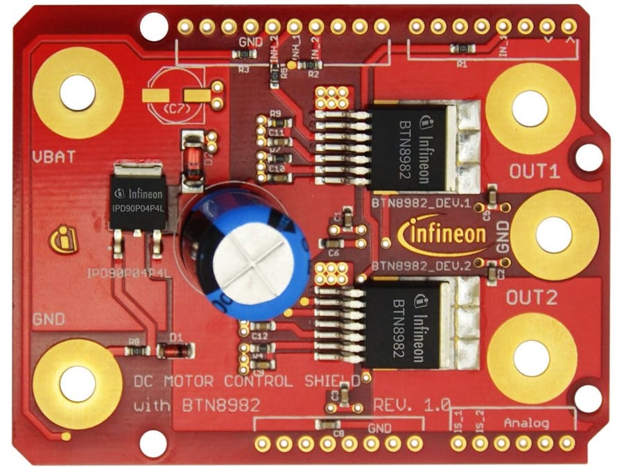
A closer look at the BTN8982TA Arduino shieldLet's have a look at what this actually is; the motor control shield comprises essentially two motor drivers, which could each uni-directionally control a DC motor or both could be connected together to form a half-bridge circuit and could bi-directionally control a DC motor.
Taking a closer look at each motor driverSo this small piece of pure semiconductor greatness is essentially the VIP of our shield. This is the driver which will interface controlling a high-power DC motor. It is completely unnecessary to understand the intricate details of what happens inside it, but it is absolutely mandatory to understand what signals it has to take as input, in order to get our desired outputs from it.
As you can see from the table above, we have 3 main input signals and two output signals.
Let's take a look at the inputs:
- The first input signal (IN) that's received at pin number 2 is an analog signal that tells the motor driver: how much power do we actually want to get delivered to the motor connected to it.
- The second input signal (INH) that's received at pin number 3 is a digital signal that essentially activates the motor driver. (If the signal received is logic HIGH then the motor driver is activated, however, if the signal received is logic LOW then the motor driver will go to sleep).
- The third input signal (SR) that's received at pin 5 is what dictates the slew rate of the motor connected to it. We don't really send this signal through our Arduino board. We just have to connect this pin to the ground and if we want to adjust the slew rate we could just connect some resistors between pin5 and ground.
Now that those are covered let's also have a look at the outputs:
- The first output signal OUT, which is sent out at pin 8 is essentially the analog signal that drives our motor.
- The second output signal IS, which is sent out at pin 6 is a diagnostic signal sent by the driver in case of an error such as overtemperature or over current.
For powering the motor driver itself pin 1 and pin 7 are respectively connected to ground and the power source.
Now when looking at the diagram above, you now should know what those labeled signals in those pink boxes mean. Since we're using an Arduino UNO in this project let's see which pins are connected to those signals when the shield is mounted on our Arduino board.
Let's start with the first BTN8982TA
- IS_1 is connected to A0 on the Arduino board.
- IN_1 is connected to pin number 3 on the Arduino board.
- INH_1 is connected to pin number 12 on the Arduino board.
To continue with the second BTN8982TA's connections:
- IS_2 is connected to A1 on the Arduino board.
- IN_2 is connected to pin number 11 on the Arduino board.
- INH_2 is connected to pin number 13 on the Arduino board.
So now we could actually start working with our board on a software scale by setting up these connections in our code. Now connect your board to a computer and run the Arduino IDE and let's have some fun! (In case you don't have that installed and ready click here!)
const int IS_1 = A0;
const int IN_1 = 3;
const int INH_1 = 12;

const int IS_2 = A1;
const int IN_2 = 11;
const int INH_2 = 13;

void setup() {
  pinMode(IS_1, INPUT);
  pinMode(IN_1, OUTPUT);
  pinMode(INH_1, OUTPUT);
  pinMode(IS_2, INPUT);
  pinMode(IN_2, OUTPUT);
  pinMode(INH_2, OUTPUT);

  analogWrite(IN_1, 0);
  digitalWrite(INH_1, HIGH);
  analogWrite(IN_2, 0);
  digitalWrite(INH_2, HIGH);
}
After setting up the pins, we give them an initial value, wherein the code snippet above I activate both BTN8982 drivers by sending a logic HIGH digital signal to the INH_1 and INH_2 pins, but I gave the motors an input pulse width modulated signal of 0 to keep the outputs of the drivers at 0.
Crash Course: PULSE WIDTH MODULATION
Pulse width modulation is switching power ON and OFF with a high frequency with the aim of controlling the power delivered to the devices. The ratio of ON and OFF time is called duty-cycle and this indicates the amount of power delivered to the device (in our case motors). To keep everything simple: it is just a way of quantifying the power that we are giving to the motors, where at 100% duty-cycle the motor is getting full power (we could use this when we want the motor to move at maximum speed), if we want to decelerate then we would reduce the duty-cycle and if we want to accelerate we would increase it.
When using the analogWrite function we are basically generating a pulse width modulated signal at a specific pin. The function takes in two inputs the first being the pin at which the signal is to be generated, and the second being a measure from 0 to 255, where 255 is a 100% duty cycle and 0 is basically no power at all.
What is a half-bridge and how does it workDisclaimer: Understanding this is by no means necessary to use this board, however, it should satisfy your curiosity in case you ever wonder what is actually going on here
Half Bridge Circuit:
A half-bridge circuit from a vastly simplified view is just a bunch of switches. (Now these switches aren't your everyday switches that you use for your lights ofc, they're just a *tad* more complex). Anyways the way these switches are closed/opened determines the direction of the current flowing through the DC motor's circuit.
As you could see in the series of figures above the direction of current through the motor is reversed if the green/red switches are respectively opened/closed and vice versa. In other words, through controlling the combination of the switch opening/closing the user has the capacity to control the direction of the DC motor's rotation. When using the bi-direction motor configuration each of our BTN8982TA represents one of those switch sets. (Green set and Red set)
Congrats!If you've reached this stage (and haven't bored yourself to death) then you have become an official expert on using the BTN8982TA Arduino shield and you've mastered the art of using it to control high power DC motors in three separate configurations:
- 1 motor unidirectionally
- 2 motors unidirectionally
- 1 motor bidirectionally
Your dedication is only matched by that of the ancient myths. I am proud of your achievement and you should be too! Before parting ways I would like to propose having a look at the other protips/projects on our page, on your road to becoming the ULTIMATE MAKER!


Comments