

Hardware components | ||||||
 |
| × | 1 | |||
 |
| × | 1 | |||
 |
| × | 1 | |||
 |
| × | 1 | |||
 |
| × | 13 | |||
Software apps and online services | ||||||
 |
| |||||
Hand tools and fabrication machines | ||||||
 |
| |||||
Lately I've played with the idea of recycling old junk to use as components. If you have old stuff you have no use for any more, you can easily take them apart and find some stuff that could become useful in projects! What's more, it's a cheap solution to get parts for your projects!
Reuse JoystickOne thing I've wanted was a joystick, but I noticed I had a PlayStation One Controller lying around, so it got me thinking — why not take it apart and salvage parts from it, and use the analog sticks for a joystick or something similar? As you read through this, you'll find my quest proved to be quite fruitful!
The first thing you need to do is take apart the controller. It's held together (quite tightly!) by 7 screws. Using a small screwdriver can take all the screw outs, but should cover a lot of resistance and can't get the screw out, drill into the screw.
After this, the controller should easily come apart, and you'll uncover a treasure chest of parts!
There's controller buttons, boards, motors and more! One thing I suggest you do is cut the wires in the main cable, and then the wires connecting to the main board. This board is connected to the analog sticks and the rumble motors. We'll focus on the analog sticks, but if you want to get the motors, you can do that with the exact same method we're using for the sticks — desoldering!
Desoldering the sticks is very easy, all you need is a soldering iron, and a solder sucker. If you prefer braiding for desoldering, that works too!
Desolder the pins by pressing the soldering iron against the solder. It will then melt, and take the solder off. As I'm using a solder sucker, the solder just pulls right off! Repeat for all the other pins, and be sure to clean your iron's tip every now and again to prevent it getting black marks.
When all the solder is off the pins, take the stick off the board. It will take some fiddling but you'll eventually get it off, then you've got an analog stick!
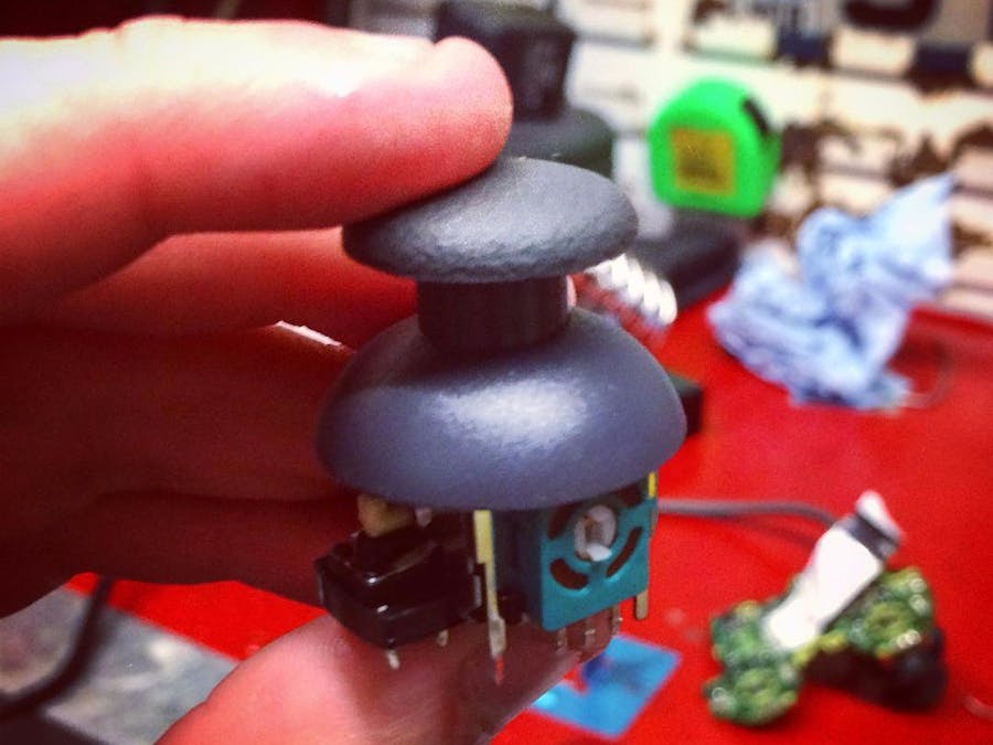
Close-Up of JoystickLet's look closer at the stick for a minute: notice it is actually comprised of three components — two potentiometers and a button! So we have three components we can interface on our robot. The potentiometers are the sticks movement, while pressing the stick will press the button attached to the stick.
Only one problem with the stick though — the pin legs are too short! So, the next thing to do is solder 8 male heads to the stick. 6 are for the potentiometers, and the remaining two are for the button.
Just apply a bit of solder onto the pins so they stick. Don't be afraid to tinker the solder a bit to make sure the pins are firmly held together. As you can see, I obviously went through a lot of trial and error to get it right!
After your pins are soldered, be sure to cover them so they're kept in place. You can use a heat shrink, or electrical tape. Here, I just used insulation tape to keep them together.
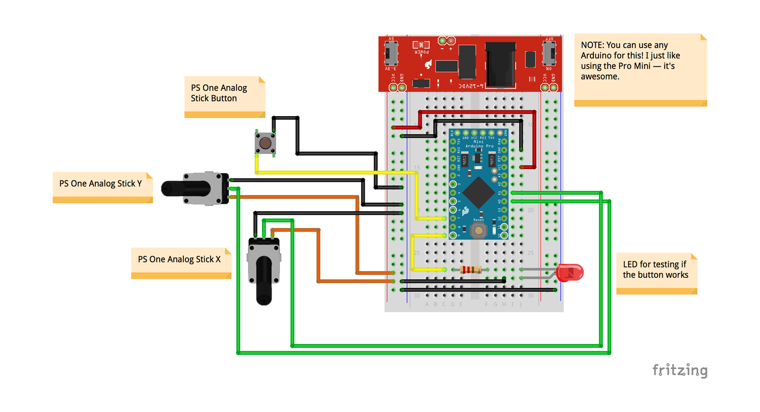
Now that we've got our analog stick ready, all we need to do now is connect it to the Arduino! I've provided a schematic in this post so you can connect it up, it's very easy to do and shouldn't require a lot of effort.
The last thing to do is to test the stick with a script, to make sure our component is okay and works. Considering we have three components on the stick, we need to test the two potentiometers and the button to make sure they're working okay. I've attached a script you can use in to test it out!
In the circuit, I've connected the analog stick's potentiometers to two analog pins, and the button to act as a pullup to turn on an LED. That's all that needs to be connected, so now we can use the code.
Be aware that in my circuit, I've used the Arduino Pro Mini. If you don't have one, don't panic! Just use any Arduino, I'm just a fan of the Pro Mini. ;-)
Test the CodeWith the code provided in this project, we can then try out the potentiometers via Serial, and make the LED turn on if the button is pressed on the analog stick. Our stick should work nice and fine, and thus we have a new component in our arsenal!
From start to finish, we've taken an old piece of tech, taken it apart, and found a brand new use for it. Hopefully this will spur you to re-use more old junk tech you find, and use it for your projects!
If you enjoyed this post, be sure to follow me on Twitter to stay up to date, and if you want to see more content like this, feel free to pledge to my Patreon or send me a donation by PayPal. Every penny is helpful and helps me keep making stuff!
Have fun!


_3u05Tpwasz.png?auto=compress%2Cformat&w=40&h=40&fit=fillmax&bg=fff&dpr=2)


Comments