



Hardware components | ||||||
 |
| × | 1 | |||
 |
| × | 1 | |||
 |
| × | 1 | |||
| × | 1 | ||||
| × | 1 | ||||
We recently wrapped up a project that sits right at the intersection of physical security and embedded Linux. A client in the logistics sector approached us with a specific problem: they had a network of unattended pickup points where users needed to collect parcels, but the existing lockers used outdated RFID cards that were easily cloned, and the backend had no real-time visibility.
They needed a system that allowed one-time access codes, remote monitoring, and the ability to update lockers over the air. The hardware choice was obvious: a Raspberry Pi Compute Module 4. But the implementation required careful planning around power management, peripheral control, and fail-safe operations.
Here is how our engineers approached the build, the components we selected, and the pitfalls we hit along the way.
## Why Raspberry Pi?
The client wanted a cloud-connected device that could handle HTTPS requests, run a local database for offline fallback, and manage multiple I/O expanders simultaneously. An MCU like the ESP32 could handle the networking, but it would struggle with the complexity of the user interface and the local encryption logic we needed.
The Raspberry Pi CM4 gave us the headroom. It runs a custom Yocto image (we avoided Raspbian for production), which boots in under 5 seconds and gives us full control over the root filesystem. This is critical for security—we didn't want any unnecessary services running on the device.
## The Component List
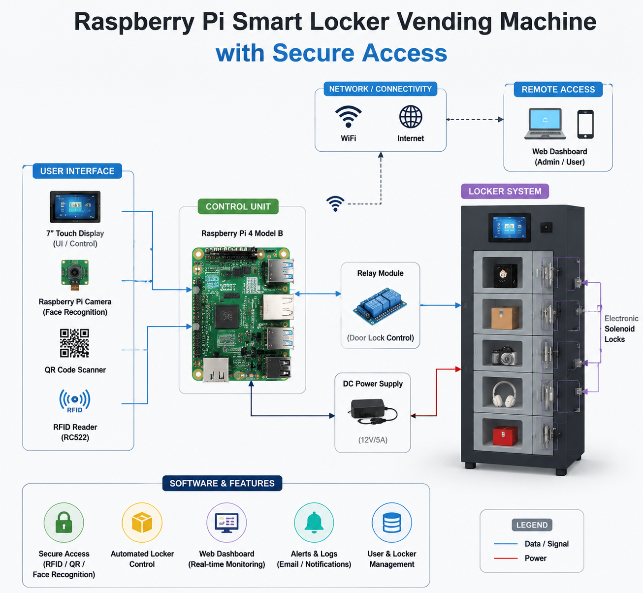
This isn't a "buy this kit and plug it in" project. We designed a custom carrier board for the CM4 because the standard IO board was too bulky for the locker chassis. Here is what went into the final prototype:
- **Raspberry Pi Compute Module 4 (2GB RAM, 8GB eMMC)** – The brain. The eMMC storage ensures we don't have SD card corruption issues in a high-vibration environment.
- **Custom Carrier Board** – Designed in KiCad. It breaks out the GPIOs, handles power regulation (12V input stepped down to 5V for the Pi), and includes a MAX485 transceiver for RS-485 communication to the locker control boards.
- **MDB Protocol Interface** – This was key. The vending machine industry uses the MDB (Multi-Drop Bus) protocol for communication between the controller and peripherals. We used a dedicated MDB master IC to handle the handshake, so the Pi didn't have to bit-bang the timing-sensitive protocol.
- **Electronic Locks (12V Solenoid Type)** – Each locker door has a solenoid lock. We drive these via a ULN2803 Darlington array, controlled by GPIO expanders over I2C.
- **PN532 NFC Module** – For physical card tap-in as a backup to the mobile app.
- **4G LTE Cat 4 HAT** – For cellular fallback. The client's locations don't all have reliable Wi-Fi, and we couldn't rely on the venue's network security.
- **Door Position Sensors (Magnetic Reed Switches)** – These are wired directly to the GPIO pins with pull-up resistors. We need to know if the door is actually closed, not just if the lock is engaged.
## The Secure Access Logic
The core requirement was secure access. We didn't want to just send a "unlock" command to the Pi and hope it was authentic. We implemented a challenge-response authentication mechanism.
Here is how it works:
1. The user scans a QR code on the locker screen or taps an NFC card.
2. The Raspberry Pi generates a random 128-bit challenge string and sends it to the cloud backend via MQTT over TLS.
3. The backend signs the challenge with the user's private key (stored in the user's app) and returns the signature along with the locker ID and a time-bound token.
4. The Pi verifies the signature using the public key stored in its secure element (an ATECC608A crypto chip). This chip handles the ECDSA verification, so the Pi's CPU isn't doing heavy crypto math.
Only after the signature is verified locally does the Pi trigger the GPIO to open the lock. This means even if the network is down, the Pi can still validate a previously issued token (with a 5-minute expiry) and unlock the door. This offline capability was a huge win for the client—their previous system was completely bricked during network outages.
## The "Hackster" Moment: Getting the Hardware to Play Nice
If you've done any work with solenoids and Raspberry Pis, you know the pain of back-EMF. When you cut power to a 12V solenoid, it generates a voltage spike that can travel back through the driver and reset the Pi. We initially spec'd a standard flyback diode across the solenoid, but we were still seeing random reboots.
The issue wasn't the diode—it was the ground plane. On our first PCB revision, the high-current return path for the solenoids ran directly under the Pi's power regulator. The voltage drop during the solenoid's inrush current (which is about 2A for 50ms) was causing the 5V rail to dip below 4.5V.
**The fix:** We re-routed the ground plane to create a star topology. The high-current path now returns directly to the 12V power input, completely isolated from the Pi's logic ground. We also added a bulk 4700µF capacitor to the 12V rail to handle the inrush. This solved the reboot issue permanently.
## Firmware and Backend
We wrote the firmware in Rust. Why Rust? Memory safety. The Pi is running a network-facing service, and we didn't want to deal with buffer overflows in C. The main loop is straightforward:
- Poll the NFC reader and QR scanner.
- Listen to MQTT topics for commands.
- Check door sensor states every 100ms.
- Report status back to the cloud via MQTT QoS 1.
The backend runs on AWS IoT Core. We used device shadows to maintain the state of each locker. This allows the client to query "what is the status of locker 17?" without sending a direct request to the Pi—they just query the shadow, which the Pi updates every 30 seconds or on any event.
## 3D Design and Prototyping
We didn't just hand over a PCB. We designed the entire mounting bracket and the bezel for the touchscreen in Fusion 360. The CM4 carrier board sits in a custom aluminum housing that acts as a heat sink. The Pi CM4 can get warm under load, especially in an unventilated locker, so we attached a thermal pad to the SoC and bolted it directly to the metal chassis.
We 3D printed the first iteration of the bezel in PETG to test the fit, then sent the final design to a local CNC shop for aluminum fabrication. The prototype unit was fully assembled in our lab in India and shipped to the client in the UK for a pilot deployment.
## Final Thoughts
This project proved that the Raspberry Pi is more than a hobbyist board—it's a legitimate production platform if you treat it like one. The key is not to rely on the stock OS or the standard IO board. Custom carrier boards, proper power sequencing, and secure boot are non-negotiable for commercial deployment.
If you are looking for a **raspberry pi developer** who understands the difference between a prototype and a product, our team has the experience. We handle the full stack: firmware, PCB layout, 3D design, and we can ship you a fully assembled and tested prototype that is ready for mass production.
We learned a lot about MDB protocol quirks and solenoid power management on this one. If you are building a vending machine, a kiosk, or any access-control system, feel free to reach out. We are happy to share the schematics and the lessons learned.


Comments