Slight revision, denoted by italics.
I first discovered Nixie clocks by accident while web surfing. After reading through several Instructables, creators web pages, and how Nixies work, I decided to make one from scratch as well. I did use other authors code snippets for certain elements of the clock. In my learning, I thought I would be able to create and etch my own circuit boards. After several trials and failures I deemed this was not a viable option. I considered using OSH Park at first, but they did not have a program to draw the diagram or design the PCB. I stumbled across EasyEDA, then found that I can also prototype PCBs and have them made. It took sometime to get used to EasyEDA but once I did I found it very simple to work with.
This project took considerable investment of time on my part as I had never coded in C language and I have full time job. I read several books on C+ and found them difficult to understand without hands on knowledge. I decided to dive into Arduino by first playing with LEDS and Examples. I furthered my learning of shift registers using a basic kit then had to study GRA and AFCH's work intensely to learn how the 32 bit shift registers work. I also relied heavily on forum users helping me out, specifically pcbbc and 6v6gt. Without your guidance I would have lost a lot more hair.
As this is my very first prototype I've already discovered some flaws about it I do not like.
- Nixie Tubes are too close together. This is going to make it difficult to fit my first clock box around the tubes. I planned and using some old cedar fence pickets that have a very nice weathered/worn look.
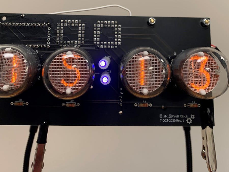
- I should have made relief holes in the PCB for the Nixie tube backs, where the glass is blown. This makes the Nixie tubes stand fairly high and creates an issue with LED blinker length.
- Still thinking of Nixie tube replacement ease. I did prototype soldering on female pins to the PCB and male connector pins onto the legs of the Nixie. This really made the Nixie tubes tall on the board, so I scrapped that idea. Plan to implement another scheme of this idea in the future.
- Silk screen layout incorrect for HV power supply. This can be easily fixed, but I almost sent 170VDC to the Itsy Bitsy! Thankfully I caught the error before plugging in.
- I'd prefer the HV power supply to mount and solder directly to the prototype PCB. I used hooked up wire to make connections this time. Will investigate the LUMOS SK design for more solderability.
- I need to rethink my PCB layout and routing.
- I didn't implement a way to change the time display. Only way to do so is, access the code of the Itsy Bitsy, and recompile. This was a large error in my design process.
- Started to code a revised sketch which will enable changing the hours and minutes. Will add sketch once finished.
- Adding additional code to sketch for a Nixie de-sputtering routine. I am calling this a burn cycle.
- Used an old steel first aid kit box to house my clock. This is themed after the awesome Fallout video game series. I am having permanent decals made to attach to the box later. Also using Civil Defense emblem on the face.
Please see this EasyEDA link for the schematic and PCB.
Schematic/PCB


Comments