


Hardware components | ||||||
 |
| × | 1 | |||
Software apps and online services | ||||||
| ||||||
This is a tiny power meter. You just connect your power source to the input and your load to the output, and it will measure current, voltage, and wattage, then display this value on a small OLED screen..
On the electronics side, it's powered by an XIAO ESP32-C3 paired with an INA226 current sensor. The measured values are then displayed on the tiny OLED screen.
Some features of the Xiao power meter
Up to ±10 A current measurement,
Senses Bus Voltages from 5 to 36 V
Parts Used- SeeedStudio XIAO ESP32C3
- 2*XT60PW-M
- OLED 0.96
- LM317AG-TN3-R
- 3*100NF SMD capacitor
- INA226AIDGSR
- 0.005 ohm resistor
- 200R resister
- 330R resister
- 3*10K resistor
- 4*M3x10mm screw
You can find all the BOMs for the PCB attached below
INA226 Current SensorThe INA226 is a high-precision current, voltage, and power monitoring sensor that communicates over the I²C bus. It measures the voltage drop across a shunt resistor to calculate current, and also monitors the bus voltage, allowing it to compute power consumption in real time. With features like programmable averaging, alert thresholds, and high accuracy, it is widely used in battery management systems, power supply monitoring, and embedded projects where precise energy measurement is required.PCB & Enclosure design
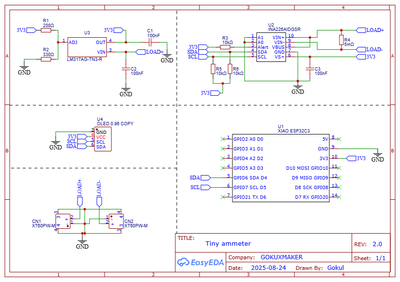
The project is not that complicated due to the small number of components, thanks to the clever design of the INA226 IC. Here is the schematic of this circuit. The communication between INA226 and OLED to Xiao is done through I2C, This circuit is powered by the input voltage, and XT60 connectors are used as input and output.I used EasyEDA to design this PCB. You find the build files attached below.
Encosoure designI used Autodesk Fusion 360 to design the enclosure. I was able to export the STEP file of the PCB using EasyEDA Pro. I also made sure the wall thickness is no less than 0.8 mm. The enclosure is a two-part design. which is held together using four M3x10mm screws
Getting the manufacturing of the PCB and enclosureI used JLCPCB for manufacturing the PCB. I chose the white colour with ENIG finish for the PCB and JLC3DP for 3D printing the enclosure. The enclosure is printed in nylon MFJ, which makes the project look almost like a commercial product.Code
#include <Wire.h>
#include <Adafruit_SSD1306.h>
#include <Adafruit_INA226.h>
// OLED setup
#define SCREEN_WIDTH 128
#define SCREEN_HEIGHT 64
#define OLED_RESET     -1
#define SCREEN_ADDRESS 0x3C
Adafruit_SSD1306 display(SCREEN_WIDTH, SCREEN_HEIGHT, &Wire, OLED_RESET);
// INA226 setup
Adafruit_INA226 ina226 = Adafruit_INA226();
float busvoltage = 0;
float current_mA = 0;
float power_mW = 0;
void setup() {
Serial.begin(115200);
// Initialize INA226
if (!ina226.begin()) {
Serial.println("Failed to find INA226 chip");
while (1) { delay(10); }
}
// Calibration: 0.005 ohm shunt resistor, max expected current ~10A
// (adjust the 10.0 value for your max current to improve accuracy)
ina226.setCalibration(0.005, 10.0);
// Initialize OLED display
if (!display.begin(SSD1306_SWITCHCAPVCC, SCREEN_ADDRESS)) {
Serial.println("SSD1306 allocation failed");
for (;;);
}
display.clearDisplay();
display.setTextColor(WHITE);
display.setTextSize(1);
display.display();
}
void loop() {
// Read data from INA226
busvoltage = ina226.readBusVoltage();   // Volts
current_mA = ina226.readCurrent() * 1000; // A → mA
power_mW   = ina226.readPower() * 1000;   // W → mW
// Show data on OLED
display.clearDisplay();
display.setCursor(0, 0);
display.setTextSize(2);
display.print("V");
display.setCursor(20, 0);
display.setTextSize(2);
display.print(busvoltage, 2);
display.setTextSize(1);
display.print("V");
display.setCursor(0, 25);
display.setTextSize(2);
display.print("A");
display.setCursor(20, 25);
display.setTextSize(2);
display.print(current_mA, 1);
display.setTextSize(1);
display.print("mA");
display.setCursor(0, 50);
display.setTextSize(2);
display.print("W");
display.setCursor(20, 50);
display.setTextSize(2);
display.print(power_mW, 1);
display.setTextSize(1);
display.print("mW");
display.display();
delay(1000); // update every second
}
Uses Adafruit_INA226 library → install from Library Manager.
ina226.setCalibration(0.005, 10.0); → first param is your shunt resistor (5 mΩ), second is your max expected current in Amps.
Example: if your system draws max 20A, change 10.0 to 20.0.
Readings:
readBusVoltage() → Volts
readCurrent() → Amps
readPower() → WattsAssembly
The first step is to start working on the components according to the schematics.
Solder the XIAO ESP32C3 after programming
The INA226 is a high-side current and power monitor IC. To calculate current when using a 0.005 Ω (5 mΩ) shunt resistor, you need to know how the INA226 measures:
It measures shunt voltage (Vshunt) across the resistor.
- It measures shunt voltage (Vshunt) across the resistor.
- Current is derived as:
I=VshuntRshuntI = \frac{V_{shunt}}{R_{shunt}}I=RshuntVshunt
where
- VshuntV_{shunt}Vshunt is the differential voltage measured across the shunt resistor..
- RshuntR_{shunt}Rshunt is your shunt resistor (0.005 Ω)
- INA226 has a programmable ADC with ±81.92 mV full-scale shunt voltage range.
So with Rshunt=0.005ΩR_{shunt} = 0.005 ΩRshunt=0.005Ω:
Imax=81.92 mV0.005 ΩI_{max} = \frac{81.92 \text{ mV}}{0.005 \, Ω}Imax=0.005Ω81.92 mV Imax=16.384 AI_{max} = 16.384 \, AImax=16.384A
So the maximum measurable current with this shunt is about 16.38 A
Finally, solder the OLED screen using some header pins. Ensure the OLED screen is positioned correctly to cover the screen window.
Finished the assembly by placing the PCB onto the enclosure and securing everything with M3 screws
TestingLet's test this device. For that, connect the input from the voltage source using the XT60 male connector.Then connect the output to the load. Now you can measure the voltage values in it.
The XT60 connector allows you to create a custom connector, such as a DC jack to an XT60 connector, making it a useful tool for testing projects. Additionally, because of its design, the XT60 is well-suited for FPV drone applications.
Lastly, I want to extend a big thank you to JLC3DP for sponsoring this project


_t9PF3orMPd.png?auto=compress%2Cformat&w=40&h=40&fit=fillmax&bg=fff&dpr=2)


Comments