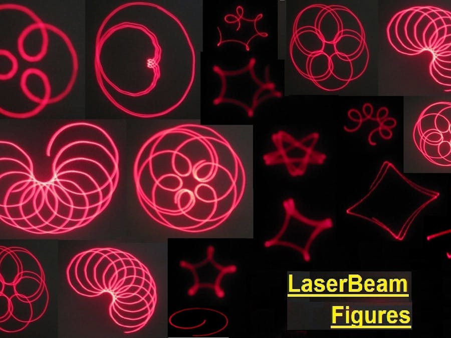
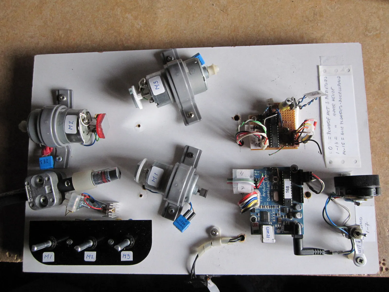
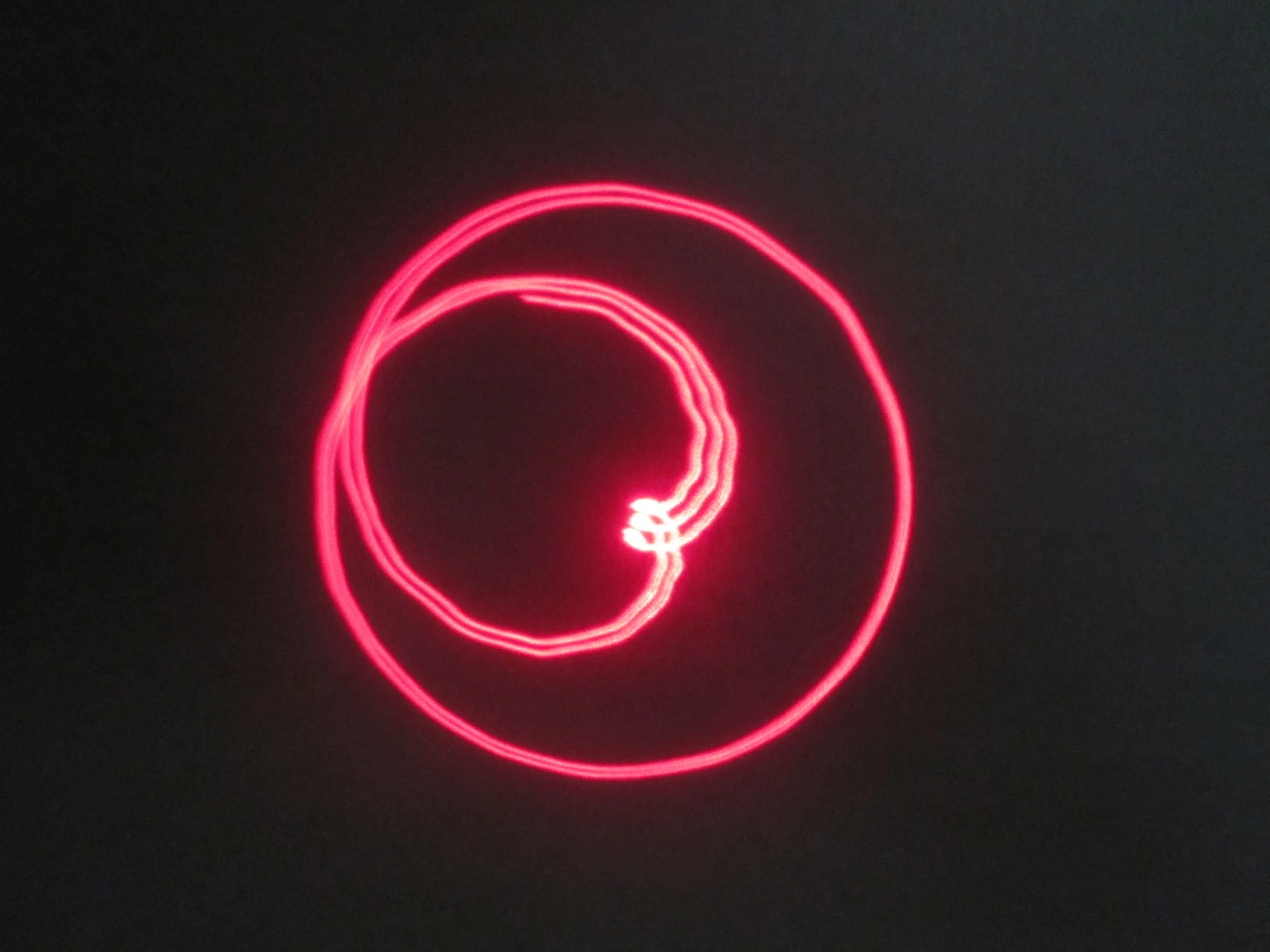
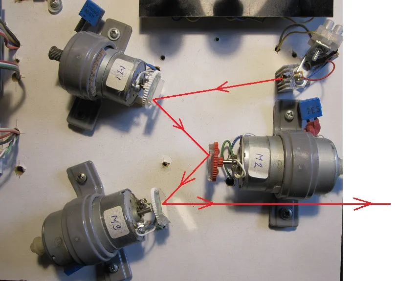
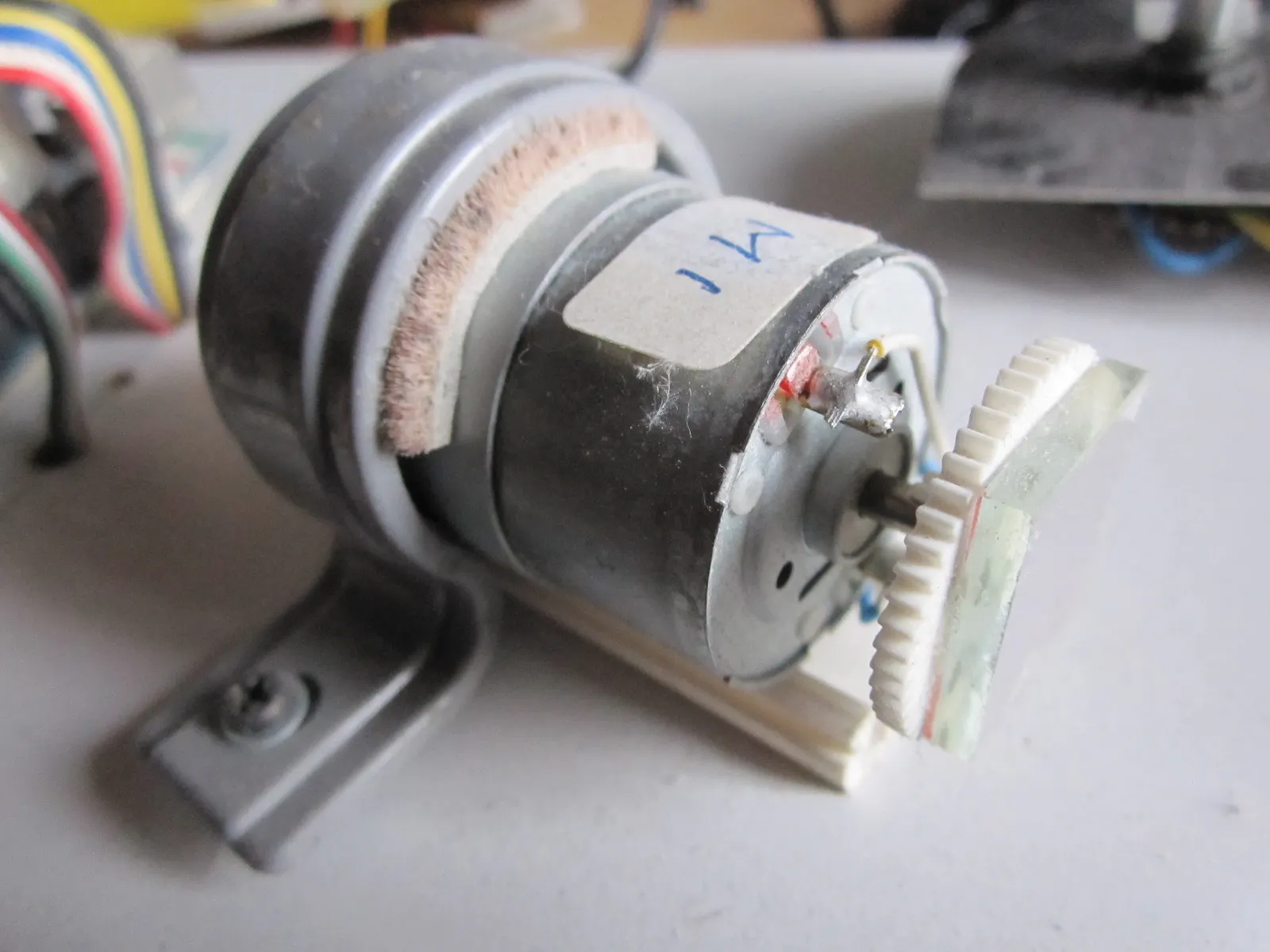
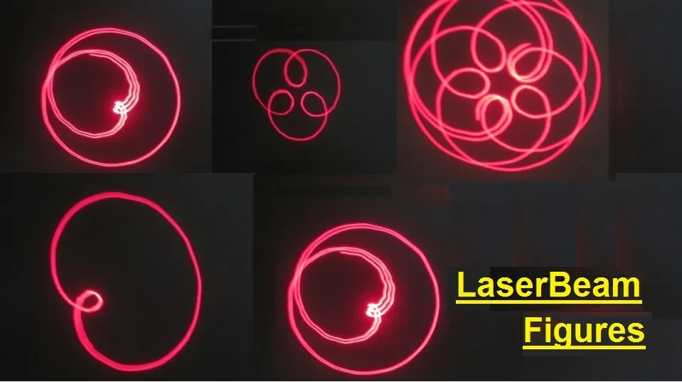
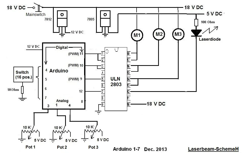
// LaserBeam with 3 Mirrors on 3 Electric motors
// Declarations :
int DataIn;
int PosSelector; // Position of Selector (16-positions)
int Figure;
int LoopCounter; // Determines time duration off 1 figure during "Show01()"
int Sm1, Sm2, Sm3; // Speed motor 1 , 2 en 3 (=Output of PWM)
int Pin4 = 4; // One of the 4 inputs for the Selector
int Pin5 = 5; // One of the 4 inputs for the Selector
int Pin6 = 6; // One of the 4 inputs for the Selector
int Pin7 = 7; // One of the 4 inputs for the Selector
int Motor1 = 9; // PWM-output for Motor
int Motor2 = 11; // PWM-output for Motor
int Motor3 = 10; // PWM-output for Motor
int Laser=12; // Digital output for Laser diode
void setup()
{ Serial.begin(9600); // Preparation Serial Communication
pinMode(Pin4, INPUT); digitalWrite (Pin4, HIGH); // Internal Pullup
pinMode(Pin5, INPUT); digitalWrite (Pin5, HIGH); // Internal Pullup
pinMode(Pin6, INPUT); digitalWrite (Pin6, HIGH); // Internal Pullup
pinMode(Pin7, INPUT); digitalWrite (Pin7, HIGH); // Internal Pullup
digitalWrite (Laser, HIGH); // Laser always on !!!
pinMode(Motor1, OUTPUT);
pinMode(Motor2, OUTPUT);
pinMode(Motor3, OUTPUT);
pinMode(Laser, OUTPUT);
LoopCounter=0;
Figure=999;
PosSelector=0;}
void loop()
{ ReadDigitalInputs();
// Display(); // Used only for making nice Figures
switch (PosSelector)
{ case 0: ReadPotmeters(); break;
case 1: Figure01(); break;
case 2: Figure02(); break;
case 3: Figure03(); break;
case 4: Figure04(); break;
case 5: Figure05(); break;
case 6: Figure06(); break;
case 7: Figure07(); break;
case 8: Figure08(); break;
case 9: Figure09(); break;
case 10: Figure10(); break;
case 11: Figure11(); break;
case 12: Figure12(); break;
case 13: Figure13(); break;
default: Show01(); break;}} // Positions 14 en 15 give all figures !!!!
void Show01()
{ LoopCounter++;
// Display();
delay(500); // with delay(500) avery Figure takes 5 seconden (without Display())
if (LoopCounter>0) {if (LoopCounter<11){Figure01();}} //
if (LoopCounter>10) {if (LoopCounter<21){Figure02();}} //
if (LoopCounter>20) {if (LoopCounter<31){Figure03();}} //
if (LoopCounter>30) {if (LoopCounter<41){Figure04();}} //
if (LoopCounter>40) {if (LoopCounter<51){Figure05();}} //
if (LoopCounter>50) {if (LoopCounter<61){Figure06();}} //
if (LoopCounter>60) {if (LoopCounter<71){Figure07();}} //
if (LoopCounter>70) {if (LoopCounter<81){Figure08();}} //
if (LoopCounter>80) {if (LoopCounter<91){Figure09();}} //
if (LoopCounter>90) {if (LoopCounter<101){Figure10();}} //
if (LoopCounter>100) {if (LoopCounter<111){Figure11();}} //
if (LoopCounter>110) {if (LoopCounter<121){Figure12();}} //
if (LoopCounter>120) {if (LoopCounter<131){Figure13();}} //
if (LoopCounter>130) {LoopCounter=0;}}
void Figure01() // Rotating (small) stick
{ Figure=01;
Sm1=171; Sm2=38; Sm3=253;
analogWrite(Motor1, Sm1);
analogWrite(Motor2, Sm2);
analogWrite(Motor3, Sm3);}
void Figure02() // Propellor 4 blades
{ Figure=02;
Sm1=62; Sm2=30; Sm3=255;
analogWrite(Motor1, Sm1);
analogWrite(Motor2, Sm2);
analogWrite(Motor3, Sm3);}
void Figure03() // Rotating dot
{ Figure=03;
Sm1=33; Sm2=0; Sm3=0;
analogWrite(Motor1, Sm1);
analogWrite(Motor2, Sm2);
analogWrite(Motor3, Sm3);}
void Figure04() // Ovals Changing in size
{ Figure=04;
Sm1=199; Sm2=212; Sm3=202;
analogWrite(Motor1,Sm1);
analogWrite(Motor2, Sm2);
analogWrite(Motor3, Sm3);}
void Figure05() // Rotating Ovals
{ Figure=05;
Sm1=53; Sm2=255; Sm3=255;
analogWrite(Motor1,Sm1);
analogWrite(Motor2, Sm2);
analogWrite(Motor3, Sm3);}
void Figure06() // Flower 5 petals
{ Figure=06;
Sm1=138; Sm2=0; Sm3=57;
analogWrite(Motor1,Sm1);
analogWrite(Motor2, Sm2);
analogWrite(Motor3, Sm3);}
void Figure07() // Square stretched
{ Figure=07;
Sm1=48; Sm2=42; Sm3=0;
analogWrite(Motor1,Sm1);
analogWrite(Motor2, Sm2);
analogWrite(Motor3, Sm3);}
void Figure08() // Rotating Circles
{ Figure=8;
Sm1=255; Sm2=255; Sm3=255;
analogWrite(Motor1,Sm1);
analogWrite(Motor2, Sm2);
analogWrite(Motor3, Sm3);}
void Figure09() // Circles Changing in size
{ Figure=9;
Sm1=0; Sm2=226; Sm3=255;
analogWrite(Motor1,Sm1);
analogWrite(Motor2, Sm2);
analogWrite(Motor3, Sm3);}
void Figure10() // Circle with internal circle
{ Figure=10;
Sm1=0; Sm2=52; Sm3=255;
analogWrite(Motor1,Sm1);
analogWrite(Motor2, Sm2);
analogWrite(Motor3, Sm3);}
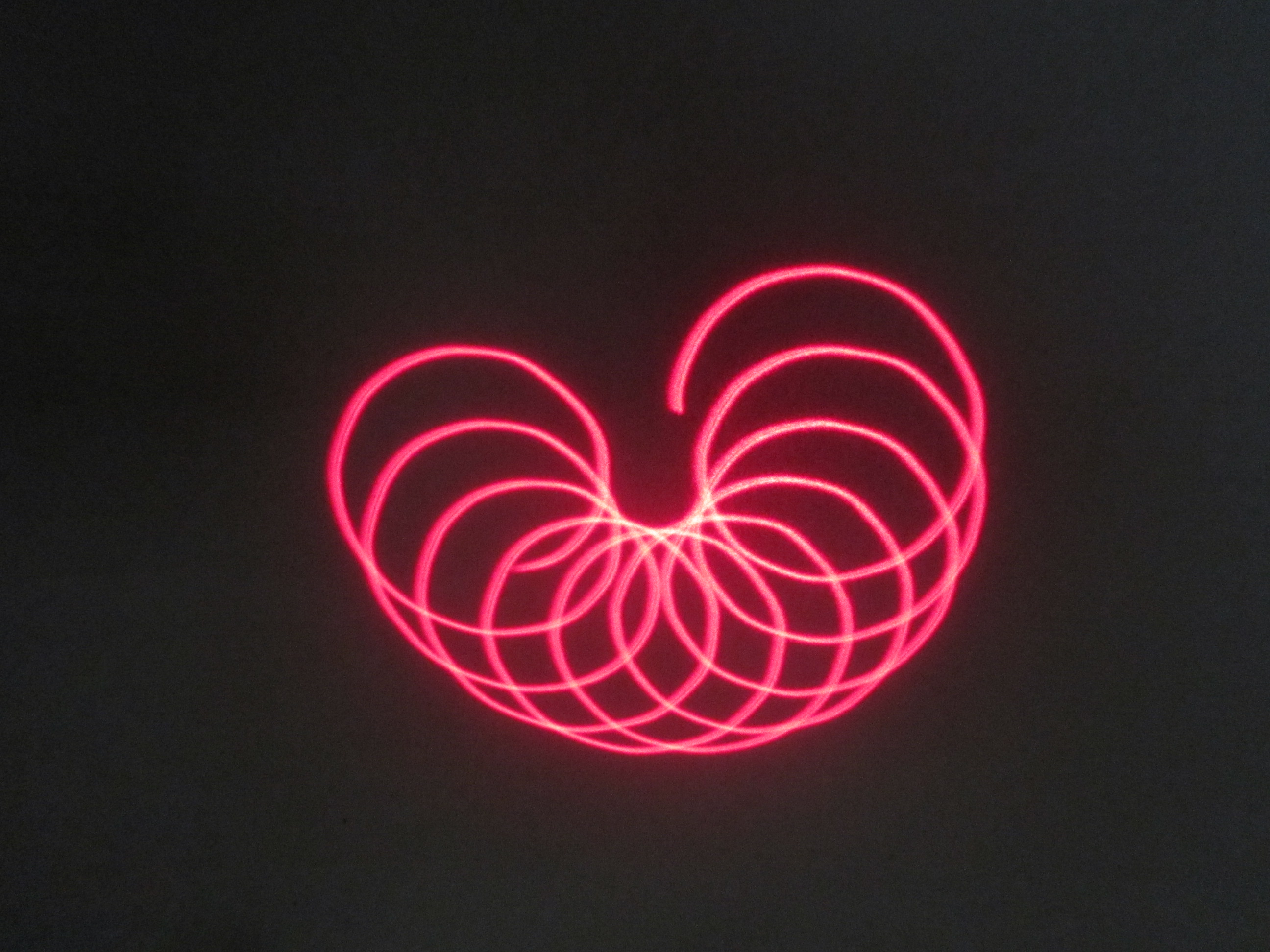
void Figure11() // Rotating Apple
{ Figure=11;
Sm1=0; Sm2=77; Sm3=255;
analogWrite(Motor1,Sm1);
analogWrite(Motor2, Sm2);
analogWrite(Motor3, Sm3);}
void Figure12() // Rotating Circles
{ Figure=12;
Sm1=0; Sm2=42; Sm3=255;
analogWrite(Motor1,Sm1);
analogWrite(Motor2, Sm2);
analogWrite(Motor3, Sm3);}
void Figure13() // Star
{ Figure=13;
Sm1=255; Sm2=105; Sm3=0;
analogWrite(Motor1,Sm1);
analogWrite(Motor2, Sm2);
analogWrite(Motor3, Sm3);}
void ReadDigitalInputs() // Read 4 Switches. PosSelector has values from 0 to 15
{ PosSelector=0;
DataIn=digitalRead(Pin4); if (DataIn==LOW){PosSelector=1;} //
DataIn=digitalRead(Pin5); if (DataIn==LOW){PosSelector=PosSelector+2;}
DataIn=digitalRead(Pin6); if (DataIn==LOW){PosSelector=PosSelector+4;}
DataIn=digitalRead(Pin7); if (DataIn==LOW){PosSelector=PosSelector+8;}}
void Display()
{ Serial.print("Motor 1 : ");
Serial.print(Sm1); // Speed of Motor (= output of PWM)
Serial.print(" Motor 2 : ");
Serial.print(Sm2); // Speed of Motor (= output of PWM)
Serial.print(" Motor 3 : ");
Serial.print(Sm3); // Speed of Motor (= output of PWM)
Serial.print(" LoopCounter : ");
Serial.print(LoopCounter);
Serial.print(" PosSelector= ");
Serial.println(PosSelector);
// Serial.print(" Figure : ");
// Serial.println(Figure);
}
void ReadPotmeters() // Figure15
{ Sm1=analogRead(4); Sm1=Sm1/4;
analogWrite(Motor1, Sm1);
Sm2=analogRead(1); Sm2=Sm2/4;
analogWrite(Motor2, Sm2);
Sm3=analogRead(3); Sm3=Sm3/4;
analogWrite(Motor3, Sm3);}


_ztBMuBhMHo.jpg?auto=compress%2Cformat&w=48&h=48&fit=fill&bg=ffffff)


Comments