

Hardware components | ||||||
_ztBMuBhMHo.jpg?auto=compress%2Cformat&w=48&h=48&fit=fill&bg=ffffff) |
| × | 1 | |||
| × | 2 | ||||
 |
| × | 1 | |||
I'm currently working on a sensor-centric pan/tilt system using 2 servos with real-time potentiometer positional data on each servo as part of a larger project. I was looking for a way to have different "modes" of scanning depending on the sensor attached. Sparkfun's Servo Trigger firmware seemed like a great place to start, but it only allows one servo, and has to be configured by a series of jumpers, push buttons and potentiometers. I've written this code to add another servo to the mix and allow for software configuration of the different Finite State Machines (FSMs). The Servo Trigger is based on the ATTiny84, so the Timer 1 code and some pin assignments had to be modified to work on the ATMega328 to get the appropriate 50Hz frequency for hobby servos.
Why not just use the Arduino Servo Library?About 4 days into scouring the Internet learning about 16 bit Timers, Pulse Width Modulation, Finite State Machines, Phasors, Deltas, Linear interpolation and lions and tiger and bears, I asked myself this same question. Here's what kept me going:
- Although I'll freely admit, I had never heard of an finite state machine before I started this project! The Servo Trigger firmware was already set up with built in logic for FSMs and the more I read, the more I liked the idea of knowing "where" a servo was. Also, I think it will mesh nicely with a potentiometer feedback system I have planned for the next project.
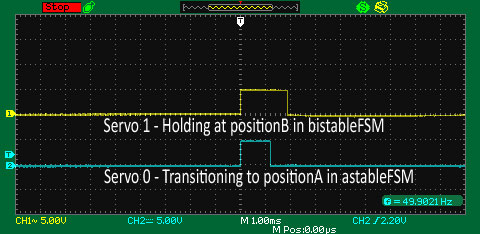
- Complete control over the pulse width driving the servos, down to the microsecond--no jittery servos here. My inexpensive oscilloscope (which I'd recommend having if you're going to get into this type of development) is displaying very clean, stable pulses and the servos are running very smoothly.
- It has a small footprint. Later, if I don't need a specific FSM, or an FSM at all, I can confidently take it out of the code to save valuable memory. Upgrading the Servo Trigger to a ATMega328 gave me some breathing room, but like I stated earlier this is a small piece to a larger puzzle.
- Last, but not least: I love a challenge.
It's not perfect, but this is only the beginning. As of this writing, I've ported 3 FSMs from the original code to the G2G_FSM library: astableFSM, bistableFSM and oneshotFSM that can be configured inside the Arduino's main .ino code.
The G2G_FSM library is my proof-of-concept for future development and my door into understanding the math involved with Delta, Phasor, Linear Interpolation and FSMs in general. The main intent of this code is to help me plan my attack of a bigger project and continue my dive into this wonderful code. I hope someone finds it useful for their next project. I welcome any comments, suggestions or questions you may have.
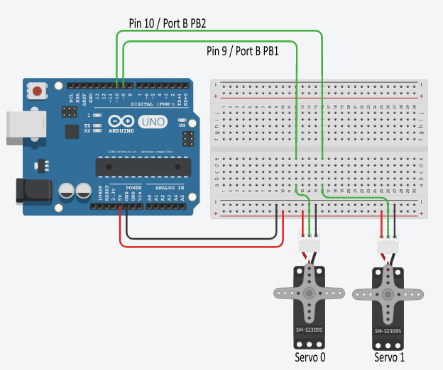
Breadboard Layout
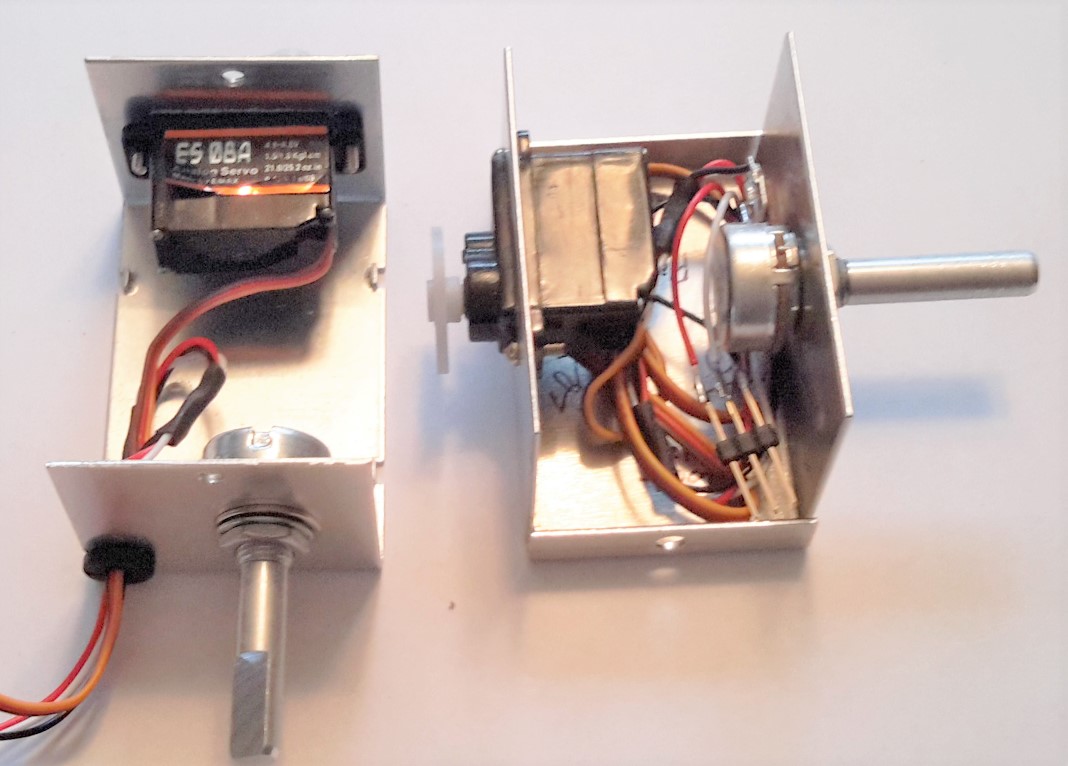
Pan/Tilt Chassis Assembly Prototype


Comments