


Hardware components | ||||||
 |
| × | 1 | |||
| × | 1 | ||||
 |
| × | 1 | |||
 |
| × | 1 | |||
 |
| × | 1 | |||
 |
| × | 1 | |||
 |
| × | 1 | |||
 |
| × | 1 | |||
Software apps and online services | ||||||
 |
| |||||
Ovality
Ovality occurs when a pipeline ‘ovals’ from its original circular shape - the pipe is no longer perfectly round. Although any pipe will oval under the right amount of loading, pipelines with high D/t ratios (diameter over thickness) are most susceptible. Ovality can be categorized as either symmetric or arbitrary out-of-roundness. The percentage of ovality – how far it is from its original circular shape - is calculated based on a simple formula.
Ovality is most likely to occur in two situations: during the pipe joint fabrication process (arbitrary out-of-roundness) and from externally applied loads during and following the pipeline construction phase (symmetric ovality). ovality. Most industry codes provide guidance on the acceptable percentage of ovality for pipeline bends
Effects of Ovality Pipeline Integrity
Excessive pipeline ovality can raise several concerns for long term pipeline integrity. Ovalized sections of pipe require less force to collapse vs round. Ovality may also have a negative effect on the integrity of the pipe coating where excessive deformation may result in damage. Even in cases where it is easy to re-round the pipe, damage can occur. Re-rounding the pipe cross section can induce a bending stress, weakening the pipe and making it more susceptible to oval again, and even collapse under stress. Early detection and correction of excessive ovality is paramount in ensuring long term pipeline safety. Prevention is key to reducing costly excavations and repairs when ovality is discovered after hydrostatic testing or anytime during the lifecycle of the pipeline.
Proposal
The idea is to build a framework that has the ability to perform in-line inspection of buried concrete pipes. The framework will utilize a combination of LiDAR and optical Imaging to carry out the inspection of the pipeline.
The device is engineered to be modular such that it can be used with land, water and air platforms. The framework can be easily integrated with existing methods
Conducting the LiDAR survey involves gathering continuous 2-D cross sections of the pipe wall. Through the compilation of these cross sections, a detailed 3-D model with high resolution is obtained. An optical imaging feed is employed to guide the robot through pipes. Moreover, the optical imaging system helps in identifying any visual anomalies.
In piping, ovalized sections of pipe require less force to collapse compared a round shaped pipe therefore through the collaboration of LiDAR imaging comprehensive image of the pipe is achieved.
My proposed framework will utilize classification algorithms to analyze the data from the pipeline and identify faults along the pipeline. Using a combination of LiDAR and mapping algoritms a 360 degree image of the pipeline will be obtained.
The design is implemented in such a way that the payload is self sufficient without the need of external input.
All the computations will be done using the KR260.
Payload setup
The major part of the payload is the Dual-resolution SEN0579 3D ToF depth camera which is equipped with a ToF image sensor with a resolution of 640*480 and uses ToF technology to capture three-dimensional information of objects and space. It can accurately measure distances up to 5m while consuming an average of only 1.2W of power. This makes it a convenient and efficient tool for 3D perception applications.
The next major component of the setup is the Grove Vision AI V2 Camera which is used to detect any visible major cracks in the pipeline using Yolov7
To identify the crack formation in the inner walls of the the pipline we use the Roboflow Crack Segmentation Dataset
# Train/val/test sets as 1) dir: path/to/imgs, 2) file: path/to/imgs.txt, or 3) list: [path/to/imgs1, path/to/imgs2, ..]
path: ../datasets/crack-seg # dataset root dir
train: train/images # train images (relative to 'path') 3717 images
val: valid/images # val images (relative to 'path') 112 images
test: test/images # test images (relative to 'path') 200 images

# Classes
names:
  0: crack

# Download script/URL (optional)
download: https://github.com/ultralytics/assets/releases/download/v0.0.0/crack-seg.zip
To annotate predictions
from roboflow import Roboflow
import supervision as sv
import cv2

rf = Roboflow(api_key="API_KEY")
project = rf.workspace().project("crack-bphdr")
model = project.version(2).model

result = model.predict("your_image.jpg", confidence=40, overlap=30).json()

labels = [item["class"] for item in result["predictions"]]

detections = sv.Detections.from_roboflow(result)

label_annotator = sv.LabelAnnotator()
mask_annotator = sv.MaskAnnotator()

image = cv2.imread("your_image.jpg")

annotated_image = mask_annotator.annotate(
    scene=image, detections=detections)
annotated_image = label_annotator.annotate(
    scene=annotated_image, detections=detections, labels=labels)

sv.plot_image(image=annotated_image, size=(16, 16))
Initializing the KR260 using the example from Kria-RoboticsAI
The Kria™ Robotics Starter Kit has a primary and secondary boot device, isolating the boot firmware from the runtime OS and application. This allows you to focus on developing and updating your application code within the application image on the secondary boot device, without having to touch the boot firmware. The primary boot device is a QSPI memory located on the SOM, which is pre-programmed (pre-loaded QSPI image) at the factory. The secondary boot device is a micro-SD card interface on the carrier card.
Setting up the Ubuntu SD Card Image
For setting up the micro-SD card, you’ll need to download the latest SD card image and then write it to the micro-SD card using an Image Flashing tool.
Go to the Install Ubuntu on AMD website, in the Choose a board tag, select Kria K26 SOMs, then click on Download 22.04 LTS (green colored) button and save the iot-limerick-kria-classic-desktop-2204-x07-20230302-63.img.xz archive on your computer.
Write the image file to the SD card with one of the methods described in setting up the sd card image reference document, for example with the Balena Etcher tool (recommended since it is available for Window, Linux, and macOS).
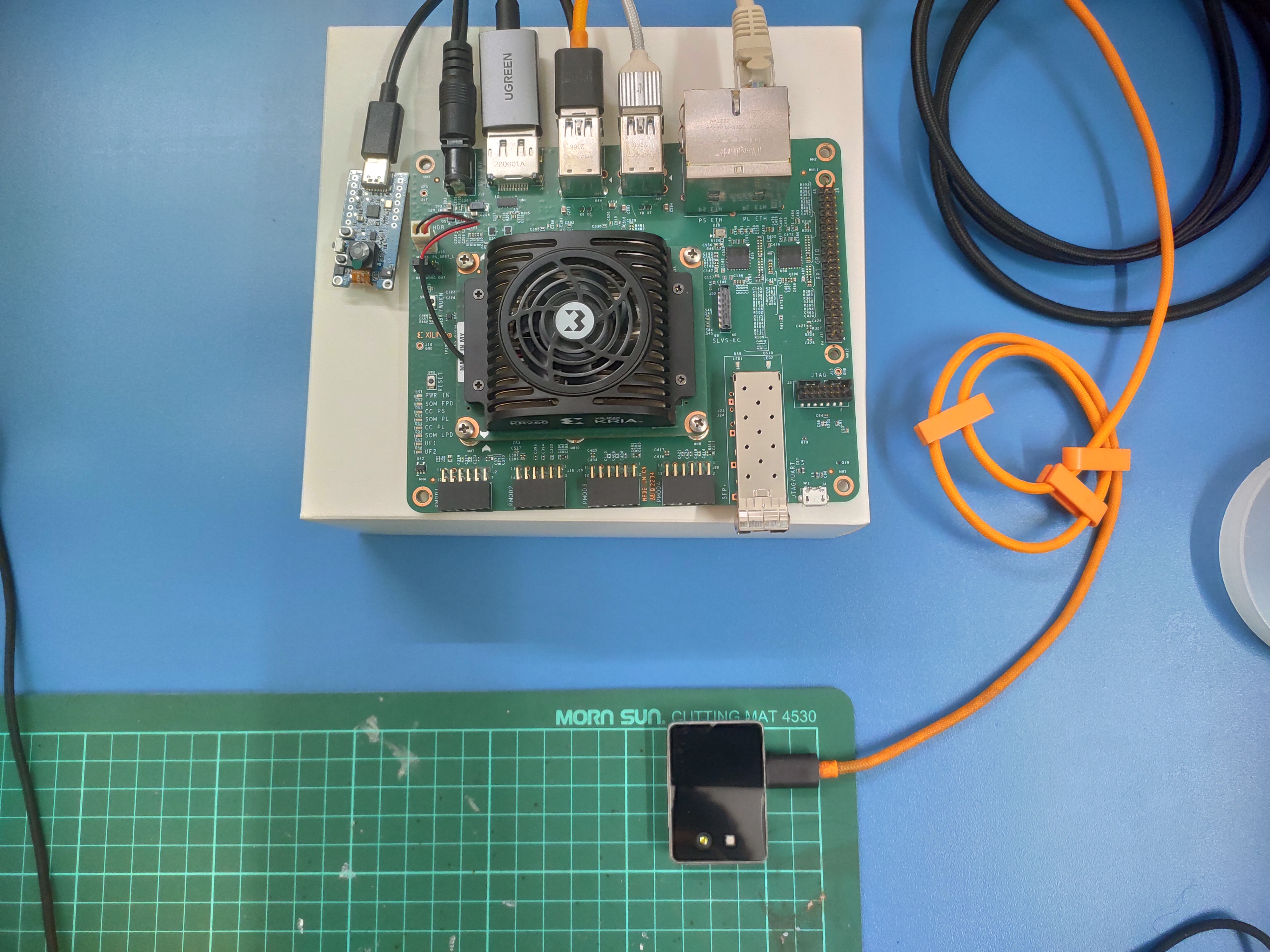
Connecting Everything
Insert the micro-SD card containing the boot image in the micro-SD card slot (J11) on the Starter Kit.
Get your USB-A to micro-B cable (a.k.a. micro-USB cable), which supports data transfer. Do not connect the USB-A end to your computer yet. Connect the micro-B end to J4 on the Starter Kit.
Connect your USB keyboard/mouse to the USB ports (U44 and U46).
Connect to a monitor/display with the help of a DisplayPort cable.
Connect the Ethernet cable to one of the PS ETH ports (the top right port: J10D) for required internet access with the factory loaded firmware.
Grab the Power Supply and connect it to the DC Jack (J12) on the Starter Kit. Do not insert the other end to the AC plug yet.
At this point, a supported USB camera/webcam can be connected to the Starter Kit.
Booting your Starter Kit
Now you can turn on your board with the KR260 Ubuntu image.
The default login credentials are:
username: ubuntu
password: ubuntu
The standard system policy requires you to change the password after the first time you log in with the default credentials.
You can login using either the traditional way over the UART serial port or a full GNOME Desktop.
Login with UART
If you want to connect a Windows PC with the target board with UART, you can use TeraTerm, for example via COM27 port (of course this will depend on your computer), as illustrated in Figure 2.
If you have a Linux host computer you can connect to the target board via PuTTY utility, you have to launch these commands (note that you have to select the second port - ttyUSB1 - among the four available ttyUSBX with X=0,1,2,3):
# from your host PC
# search for USB devices with "tty" string and
# look at the second of the list (ttyUSB1)
dmseg | grep tty# call PuTTY on ttyUSB1 for KR260
sudo putty /dev/ttyUSB1 -serial -sercfg 115200,8,n,1,NThen open a shell directly on the board and check the board IP address:
# be superuser
sudo su# check network connections
ifconfigYou should get a constant IP address, for example with value 192.168.1.186 (reported as <ip_address> in the following of this document), which you can use to transfer files with scp between your host PC and target card or to open a remote shell with ssh -X ubuntu@<ip_address> from your host PC.
Login with GNOME Desktop
To login into the GNOME Desktop, you must connect a DisplayPort monitor, as well as a USB Keyboard and Mouse to the board.
Power ON the Starter Kit by connecting the power supply to the AC plug. The power LEDs should illuminate, and after about 10-15 seconds, you should see console output on the connected display. After about a minute, the desktop login screen should appear with its traditional Jellyfish image.Note that the Starter Kit powers up immediately when you connect the AC plug to a wall. (There’s no ON/OFF switch on the board.)
If you see the heartbeat LED is active but there's no output on the monitor, check your monitor to ensure that it’s powered on and the correct input is selected.
Once logged in, you should see the default Ubuntu 22.04 LTS GNOME 3 desktop. Open a terminal and set the date as today with the following command:
sudo date -s "YYYY-MM-DD HH:MM:SS"Then verify internet connectivity with the command ping 8.8.8.8.
If you can observe that packet transmit/receive worked and there is no packet loss with the above ping command, this means your internet connectivity is working and active.
Note that without internet connectivity, you will not be able to perform the ROS-AI application steps or install the necessary tools and packages.
Install PYNQ DPU
PYNQ can be used for loading the Deep Learning Processor Unit (DPU) overlay with the CNN model of your choice for your AI inference applications.
To install PYNQ on your KR260 board you have to be superuser and run the script
install_update_kr260_to_vitisai35.shLogin in on your KR260 board and clone this repository directly in the KR260 board, so that you should have it available in the /home/ubuntu/KR260-Robotics-AI-Challenge folder.
The very first thing to do is checking with dos2unix utility all shell (*.sh) files, as they could have been moved from Windows-OS to Linux-OS file systems and viceversa, thus loosing the Unix format. In order to do so, you have to run the following commands:
#install dos2unix utility
sudo apt install dos2unix# go to the scripts folder
cd /home/ubuntu/KR260-Robotics-AI-Challenge/files/scripts# check each shell file
for file in $(find . -name "*.sh"); do
echo ${file}
dos2unix ${file}
done
Now you can start the real installation by launching the following commands (you must be superuser):
sudo su
cd /home/ubuntu/KR260-Robotics-AI-Challenge
cp files/scripts/install_update_kr260_to_vitisai35.sh /home/ubuntu
cd /home/ubuntu
source ./install_update_kr260_to_vitisai35.sh
This script will install the required debian packages, create a Python virtual environment, named pynq_venv, and configure a Jupyter portal. The process takes around 30 minutes. The script will also update the packages from Vitis-AI 2.5 (which officially supports KR260 at the moment this document is written) to the latest Vitis-AI 3.5 (not yet supporting KR260 at the moment this document is written), so you can deal with the latest material available in Vitis-AI 3.5 for what concerns Machine Learning.
You might incur in some of the following next three situations (all of them in the worst case):
During the install process you might see a window popping up, with a warning about a *xilinx-zynqmp* kernel mismatch, in that case just accept the maintainer's version and go on.
If the install procedure stops with an error, just run
source ./install_update_kr260_to_vitisai35.shagain, the second trial should take less time.
If at the end of the process you see a window like the one illustrated in Figure 5, just click OK.
Once finished successfully, you should see all the packages listed in the Included Overlays reference document already installed, including the DPU-PYNQ repository.
Now you have to reboot the board (being superuser yet):
rebootAt this time, you are strongly recommended to check the environment you have just installed by running all the examples described in Section 4.
Things to Remember
In the following of this document, before running any application, you have to become superuser and set the proper python3 virtual environment (see item 3 in the References section for more information) with these commands:
# you must always start as super user
sudo su# set the pynq environment
source /etc/profile.d/pynq_venv.shTo exit from the virtual environment, type the command:
deactivateTest PYNQ DPU with Python or C++ VART APIs
The best way to test your freshly installed environment, is by running an application.
You have three choices to run ML inference applications on the PYNQ DPU of KR260:
by opening a Jupyter Notebook (.ipynb file extension), or
by running a plain Python script (.py file extension), or
by compiling C++ modules and then launching the produced executable.
In all cases, you are using the Vitis-AI Runtime (VART) APIs, which are available both in Python (first two items) and C++ language (third item).
If you see the following message, just ignore it:
WARNING: Logging before InitGoogleLogging() is written to STDERR
F20231109 13:28:07.871371 8865 xrt_device_handle_imp.cpp:327] Check failed: r == 0 cannot set read range! cu_index 0 cu_base_addr 2147549184 fingerprint 0x101000056010407 : Invalid argument [22]
Use Jupyter Notebook
After setting the pynq_venv environment, you can go to your jupyter notebook home folder and fetch the latest notebooks:
cd $PYNQ_JUPYTER_NOTEBOOKS
# do the following command only once
pynq get-notebooks pynq-dpu -p .
Assuming the IP address of your card is 192.168.1.186 (you can easily know it by running on a terminal the command ifconfig -a), you can connect to JupyterLab via a web browser using this URL: 192.168.1.186:9090/lab or kria:9090/lab (account xilinx with password xilinx), then you can launch a notebook application, among the ones listed here:
pynq-venv) root@kria:/home/root/jupyter_notebooks# ls -l pynq-dpu/
total 95524
-rw-r--r-- 1 root root    37598 Nov  9 16:28 dpu_mnist_classifier.ipynb
-rw-r--r-- 1 root root   801364 Nov  9 16:19 dpu_mnist_classifier.xmodel
-rw-r--r-- 1 root root   199985 Nov  9 16:19 dpu_resnet50.ipynb
-rw-r--r-- 1 root root   655582 Nov  9 16:19 dpu_resnet50_pybind11.ipynb
-rw-r--r-- 1 root root 26657004 Nov  9 16:19 dpu_resnet50.xmodel
-rw-r--r-- 1 root root   137825 Nov  9 16:19 dpu_tf_inceptionv1.ipynb
-rw-r--r-- 1 root root  5921078 Nov  9 16:19 dpu_tf_inceptionv1.xmodel
-rw-r--r-- 1 root root   169209 Nov  9 16:19 dpu_yolov3.ipynb
drwxr-xr-x 2 root root     4096 Nov  9 16:19 img
-rw-r--r-- 1 root root 63212947 Nov  9 16:19 tf_yolov3_voc.xmodel
(pynq-venv) root@kria:/home/root/jupyter_notebooks# ls -l getting_started/
total 900
-rw-rw-rw- 1 root root  30068 Nov  9 15:05 1_jupyter_notebooks.ipynb
-rw-rw-rw- 1 root root  17569 Nov  9 15:05 2_python_environment.ipynb
-rw-rw-rw- 1 root root 863661 Nov  9 15:05 3_jupyter_notebooks_advanced_features.ipynb
drwxrwxrwx 2 root root   4096 Nov  9 15:05 images
(pynq-venv) root@kria:/home/root/jupyter_notebooks# ls -l pynq-helloworld/
total 9272
drwxrwxrwx 2 root root    4096 Nov  9 16:00 images
-rw-rw-rw- 1 root root 7797813 Nov  9 15:07 resizer.bit
-rw-rw-rw- 1 root root  395399 Nov  9 15:07 resizer.hwh
-rw-rw-rw- 1 root root  649101 Nov  9 15:07 resizer_pl.ipynb
-rw-rw-rw- 1 root root  639777 Nov  9 15:07 resizer_ps.ipynb
(pynq-venv) root@kria:/home/root/jupyter_notebooks# ls -l kv260
drwxrwxrwx root/root         0 2023-11-09 11:00 ./kv260/microblaze/
-rw-rw-rw- root/root      6390 2023-11-09 10:55 ./kv260/microblaze/microblaze_c_libraries.ipynb
-rw-rw-rw- root/root      7054 2023-11-09 10:55 ./kv260/microblaze/microblaze_python_libraries.ipynb
-rw-rw-rw- root/root     13143 2023-11-09 10:55 ./kv260/microblaze/microblaze_programming.ipynb
-rw-rw-rw- root/root    141256 2023-11-09 11:47 ./kv260/video/opencv_filters_webcam.ipynb
-rw-rw-rw- root/root    148997 2023-11-09 10:55 ./kv260/video/data/opencv_filters.jpg
-rw-rw-rw- root/root    284700 2023-11-09 10:55 ./kv260/video/data/sobel.jpg
-rw-rw-rw- root/root    170226 2023-11-09 10:55 ./kv260/video/data/orig.jpg
-rw-rw-rw- root/root    341406 2023-11-09 10:55 ./kv260/video/data/haarcascade_eye.xml
-rw-rw-rw- root/root    930127 2023-11-09 10:55 ./kv260/video/data/haarcascade_frontalface_default.xml
-rw-rw-rw- root/root    146789 2023-11-09 10:55 ./kv260/video/data/gray.jpg
-rw-rw-rw- root/root      4443 2023-11-09 10:55 ./kv260/video/mipi_to_displayport.ipynb
-rw-rw-rw- root/root      4060 2023-11-09 10:55 ./kv260/video/display_port_introduction.ipynb
-rw-rw-rw- root/root    284545 2023-11-09 10:55 ./kv260/video/opencv_face_detect_webcam.ipynb
Note that you can see the folder /home/root/jupyter_notebooks/kv260 only if you enabled the line bash install.sh -b KV260 during step 2 of the install_update_kr260_to_vitisai35.sh script.
Use Plain Python Code
In this section, you will see an example with ResNet18 CNN designed with the VART APIs in Python.
This ResNet18 application is taken from the Running ResNet18 CNN Through Vitis-AI 3.5 Flow for ML tutorial, in which a ResNet18 CNN pre-trained with the ImageNet dataset (1000 classes, RGB images of 224x224 size), was modified and fine-tuned for the CIFAR10 dataset (10 classes, RGB images of 32x32 size).
In the cifar10_tf2 folder, you can use the app_cifar10_tf2_resnet18.py application code to run inference with the modified ResNet18 on some CIFAR10 test images. The quantized model is named quantized/q_resnet18_cifar10.h5 and it was generated by running the original tutorial with Vitis-AI 3.5 release. Now, you have to compile the quantized model for the current KR260 board using the Vitis-AI compiler. Here are the various steps if you want to re-do it from scratch, otherwise you can use the already available model named compiled/kr260_cifar10_tf2_resnet18.xmodel and skip step 2, jumping directly from step 1 to to step 3:
From your host computer enter the Vitis-AI 3.5 CPU docker image and enter in the TF2 virtual environment:
# from your host computer launch the docker CPU 3.5 image
./prepare_docker.sh
./docker_run.sh xilinx/vitis-ai-tensorflow2-cpu:latest
# now you are inside docker CPU 3.5
conda activate vitis-ai-tensorflow2
Go to the cifar10_tf2 folder and launch the vitisai_compile.sh script:
# compile the CNN quantized models
bash -x ./vitisai_compile.sh kr260 ./quantized/q_resnet18_cifar10.h5 ./compiled kr260_cifar10_tf2_resnet18Prepare the test images to be used during the runtime application with the cifar10_generate_images.py script:
# you are supposed to be in cifar10_tf2 folder
# prepare the test images
bash -x ./prepare_cifar10.sh# you can exit from the docker image
exitCopy with scp -r the entire cifar10_tf2 folder directly to your KR260 board at /home/ubuntu/KR260-Robotics-AI-Challenge/files/ and then copy it also to /home/root/jupyter_notebooks/pynq-dpu/. Login to the board and run the
app_cifar10_tf2_resnet18.py application file. Here is the list of commands you should use:
# 1) turn on the target KR260, which is assumed to have IP 192.168.1.186
# 2) from your host PC copy the archive to the target board
scp -r cifar10_tf2 ubuntu@192.168.1.186:/home/ubuntu/KR260-Robotics-AI-Challenge/files/# 3) now remotely connect to target KR260 from your host PC
ssh -X ubuntu@192.168.1.186# 4) you are on the target board now
# 5) become super user and set the virtual env
sudo su
source /etc/profile.d/pynq_venv.sh
# 6) move the archive to its destination folder
cd $PYNQ_JUPYTER_NOTEBOOKS
cd pynq-dpu/
mv /home/ubuntu/cifar10_tf2 .
# 7) run the Python application
cd cifar10_tf2python3 app_cifar10_tf2_resnet18.py
cd ../You should see the following output text:
(pynq-venv) root@kria:/home/root/jupyter_notebooks/pynq-dpu/cifar10_tf2# python3 ./app_cifar10_tf2_resnet18.py
ResNet18 CNN (pre-trained with ImageNet Dataset) fine-tuned to CIFAR10 Dataset, in TensorFlow2
shapeIn   : (1, 32, 32, 3)
shapeOut  : (1, 1, 1, 10)
outputSize: 10
Classifying 5000 CIFAR10 pictures ...
Execution time: 15.0585s
Throughput: 332.0380FPS
Overall accuracy: 0.8502
number of top1 false predictions  749
number of top1 right predictions  4251
top1 accuracy = 0.8502
(pynq-venv) root@kria:/home/root/jupyter_notebooks/pynq-dpu/cifar10_tf2#
The prediction results are well aligned with the results obtained on the ZCU102 board with the Running ResNet18 CNN Through Vitis-AI 3.5 Flow for ML original tutorial. The results in terms of throughput are related to a single-thread application, as this code does not apply multi-threading (which would certainly increase the performance).
Use VART C++ APIs
In the previous sections, all of the inference runtime applications were designed with the VART APIs in Python.
In this section, you will design the inference application by using the C++ version of VART APIs. Then, you will test the prediction accuracy of the ResNet18 CNN model (q_resnet18_cifar10.h5) that was fine-tuned for the CIFAR10 dataset in the previous section (kr260_cifar10_tf2_resnet18.xmodel).
The main_int8.cc is an example of an inference application written in the C++ language. You can compile it directly on the board with build_app.sh shell script
and launch it via the Python script app_run_cifar10_cpp_code.py. You will see the filename of the input images and the predictions inferred by the CNN. You can then launch the Python script
check_runtime_top5_cifar10.py to check the average prediction accuracy.
Assuming you had already copied the cifar10_tf2 folder and set the python3 environment as explained in the previous sections, and expanded the test images archive, here are the commands to launch on the KR260 board:
# you should already have done all the next four commands from previous section
sudo su
source /etc/profile.d/pynq_venv.sh
cd $PYNQ_JUPYTER_NOTEBOOKS
cd pynq-dpu/cifar10_tf2
# compile the C++ application directly on the board
cd code
bash ./build_app.sh
# rename it
mv code run_cnn.exe
cd ..# run the C++ compiled exe
python3 ./app_run_cifar10_cpp_code.py 1> /dev/null# check prediction accuracy
python3 ./code/src/check_runtime_top5_cifar10.py -i ./cpp_cifar10_predictions.logYou should see the following output text:
(pynq-venv) root@kria:/home/root/jupyter_notebooks/pynq-dpu/cifar10_tf2# python3 ./app_run_cifar10_cpp_code.pyLaunching Inference on MNIST with C++ Compiled Executable using C++ VART APIs
OUT  size 10
IN   size 3072
IN Height 32
IN Width  32
batchSize 1
. . .
Image : dog_7149.png
top[0] prob = 0.999936  name = dog
top[1] prob = 0.000058  name = cat
top[2] prob = 0.000004  name = deer
top[3] prob = 0.000002  name = frog
top[4] prob = 0.000000  name = bird
. . .
Image : truck_485.png
top[0] prob = 0.649907  name = ship
top[1] prob = 0.306994  name = truck
top[2] prob = 0.041547  name = airplane
top[3] prob = 0.001255  name = bird
top[4] prob = 0.000218  name = dog
successfull run. Exited with  0
(pynq-venv) root@kria:/home/root/jupyter_notebooks/pynq-dpu/cifar10_tf2# python3 ./code/src/check_runtime_top5_cifar10.py -i cpp_cifar10_predictions.log
cpp_cifar10_predictions.log  has  35005  lines
number of total images predicted  4999
number of top1 false predictions  752
number of top1 right predictions  4247
number of top5 false predictions  42
number of top5 right predictions  4957
top1 accuracy = 0.85
top5 accuracy = 0.99
(pynq-venv) root@kria:/home/root/jupyter_notebooks/pynq-dpu/cifar10_tf2#
Install ROS2
The Robot Operating System (ROS) is a set of software libraries and tools for building robot applications.
You will now install ROS 2 Humble Hawksbill distribution on your Ubuntu 22.04 desktop of the KR260 target board.
First of all, boot the board and open a terminal and enter in the pynq_env as usual:
sudo su
source /etc/profile.d/pynq_venv.sh
Now you have to launch the install_ros.sh script from this repository to install ROS2:
cd /home/ubuntu/
cd KR260-Robotics-AI-Challenge/files/scripts/
source ./install_ros.sh
Also this process is quite long and you have to answers Y when prompted some times.
Test TurtleSimOnce you've installed ROS2, you can verify it by starting TurtleSim by entering the following commands in your terminal:
# set up your ROS2 environment
source /opt/ros/humble/setup.bash# launch the turtle simulator
ros2 run turtlesim turtlesim_nodeAs illustrated in Figure 6, the simulator window should appear, with a random turtle in the center. You can ignore text messages like this:
libGL error: failed to load driver: xlnx
Open another terminal and set up your ROS2 environment again. Now you will run a new node to control the turtle in the first node:
ros2 run turtlesim turtle_teleop_keyROSAI Application
In your project directory, you can see a folder labeled ROSAI, which contains a ROS2 design for controlling a robot, in this case, the turtle simulator, with an AI-based handwritten digit recognition model.
This application runs on the KR260 board and the same environment used in test turtlesim section, it was originally developed by Avnet for the TECH BRIEFS Webinar Series: How to Control Robots with Gestures and here adapted properly for the KR260 board with PYNQ.
There are two folders:
file_input, where the input images come from files.
camera_input, where the input images come from a camera.
File Input
Here are the steps to build and run the demo, which takes the input images from the files of the MNIST test dataset.
As usual, you have to become superuser and set the pynq_venv environment:
sudo su
source /etc/profile.d/pynq_venv.sh
Launch the install_rosai_file_input.sh script to install and build this application. This script also save MNIST images for testing the application (see save_images_from_MNIST_dataset.py file) and creates a workspace (shortly "ws") folder named ros2_ws_fileio. You can get more details by looking at the comments inside the script itself.
cd /home/ubuntu/KR260-Robotics-AI-Challenge/files/scripts
source ./install_rosai_file_input.sh
Set the environment and execute the demo:
# set env
source /opt/ros/humble/setup.bash
source install/local_setup.sh
# go to the source code
cd /home/root/ros2_ws_fileio# demo run
ros2 launch rosai_file rosai_file_demo_launch.pyLook at item 7 of References if you get a warning message like unable to import Axes3D.
The TurtleSim window will pop up and after some seconds the turtle will move (forward, backward, left and right) based on the command, which is a digit recognized by the MNIST CNN classifier, as illustrated in Fiure 7.
If you wish, you can remove the just build demo with the command:
rm -rf build/ install/ log/Camera Input
Here are the steps to build and run the demo that uses images from a camera as the input source. This demo was verified with a Logitech HD Pro WebCam C920 camera.
First follow what reported in the Appendix Check Your USB WebCam. Then apply the following steps:
As usual you have to become super user and set the pynq_venv environment:
sudo su
source /etc/profile.d/pynq_venv.sh
Launch the install_rosai_camera_input.sh script to install and build this application. This script creates a workspace folder named ros2_ws. A user can see the commands and related comments inside the script file.
cd /home/ubuntu/KR260-Robotics-AI-Challenge/files/scripts
source ./install_rosai_camera_input.sh
The following commands will launch the demo. Because of the way the model was trained, you need to use the images like the ones provided in the folder rosai_camera_input/black_background_images, or you can create your own images. We recommend either printing the images on paper (one image per page) or using a display device to hold up in front of the camera. Here are the commands:
# set the environment
source /opt/ros/humble/setup.bash
source install/local_setup.sh
# go to the source code
cd /home/root/ros2_ws# demo the camera run
ros2 launch rosai_camera rosai_camera_demo_launch.pyNow, the TurtleSim gets launched, and the turtle will move based on the digit identified by the model, which is using a CNN classifier.
The numbers corresponding to the movement direction are as follows:
1=Forward
2=Backward
3=Left4=Right
If you wish, you can remove the just build demo with the command:
rm -rf build/ install/ log/If you wish to run your own custom CNN model on the KR260, you have to train it and then quantize via the Vitis-AI release, and therefore you need the associated docker image.
Here is the processing flow you should do, working with Vitis-AI:
Clone the Vitis-AI 3.5 repository and build its docker image (note that the master version contains always the latest release, which is 3.5, at the moment this document is written).
- Clone the Vitis-AI 3.5 repository and build its docker image (note that the master version contains always the latest release, which is 3.5, at the moment this document is written).
Go to the [Vitis-AI 2.5 Model Zoo]((https://github.com/Xilinx/Vitis-AI/tree/2.5/model_zoo) and select some CNN model you might want to test (all those CNN models were pre-trained by AMD/Xilinx). Alternatively you can use your own custom CNN model (assuming you have already trained CNN it).
- Go to the [Vitis-AI 2.5 Model Zoo]((https://github.com/Xilinx/Vitis-AI/tree/2.5/model_zoo) and select some CNN model you might want to test (all those CNN models were pre-trained by AMD/Xilinx). Alternatively you can use your own custom CNN model (assuming you have already trained CNN it).
Quantize to fixed point and compile the CNN for the KR260 target board (note that the Model Zoo contains also the quantized model of every CNN, so you can skip this part if you like).
- Quantize to fixed point and compile the CNN for the KR260 target board (note that the Model Zoo contains also the quantized model of every CNN, so you can skip this part if you like).
Write the ML application to make inference (or predictions) either in Python or in C++ using the DPU Vitis-AI RunTime (VART) APIs to control the DPU itself via the ARM Host CPU.
- Write the ML application to make inference (or predictions) either in Python or in C++ using the DPU Vitis-AI RunTime (VART) APIs to control the DPU itself via the ARM Host CPU.
Go to the Vitis-AI 3.5 release and zip the repository to get its zip archive; alternatively, you can clone it directly:
git clone https://github.com/Xilinx/Vitis-AI.gitNow you can build directly the docker image based on CPU with TensorFlow2 with these commands:
cd Vitis-AI/docker
./docker_build.sh -t cpu -f tf2
Alternatively to that, you can pull it directly from the AMD Xilinx Docker Hub, with the command
docker pull xilinx/vitis-ai-tensorflow2-cpuYou have to use this CPU-based docker image to quantize and compile your CNN, in order to avoid any mismatch between the HW architecture (the DPU on your target board) and the SW application (the VART APIs associated with the Vitis-AI release you are using).
But if you need to re-train from scratch your CNN, it is better you do it with the GPU-based docker image of Vitis-AI 3.5, from where you can generate the floating point model in HDF5 format (typically a file with extension .h5).
Connect a Logitech HD Pro Webcam C920 camera to the USB port 'U44' of KR260 and run one of the following commands:
lsusb

v4l2-ctl --list-devices

ls /dev/vid*
and the related output text should be:
ubuntu@kria:~$ v4l2-ctl --list-devices
HD Pro Webcam C920 (usb-xhci-hcd.1.auto-1.2):
	/dev/video0
	/dev/video1
	/dev/media0

ubuntu@kria:~$ ls  /dev/vid*
/dev/video0  /dev/video1
Then you can use the following Python code to capture and show some frames:
import cv2
import numpy as np
cap = cv2.VideoCapture("/dev/video0") # check this
while(True):
    # Capture frame-by-frame
    ret, frame = cap.read()
    # Our operations on the frame come here
    gray = cv2.cvtColor(frame, cv2.COLOR_BGR2GRAY)
    # Display the resulting frame
    cv2.imshow("frame",gray)
    if cv2.waitKey(1) & 0xFF == ord("q"):
        break
# When everything done, release the capture
cap.release()
PoC and Working of the design
Mobilizing the Payload
The payload is intended to be a modular framework that can easily mobilized using mobile rovers, underwater UAVs or even drones to map super surface pipelines. The next iteration of this concept will focus in detail how the payload can specialize in integrating with the above said mobilizations.
References and assets used

Comments