
Hardware components | ||||||
| × | 1 | ||||
| × | 1 | ||||
| × | 1 | ||||
| × | 1 | ||||
 |
| × | 2 | |||
| × | 1 | ||||
 |
| × | 1 | |||
 |
| × | 1 | |||
| × | 1 | ||||
 |
| × | 1 | |||
Software apps and online services | ||||||
 |
| |||||
| ||||||
| ||||||
| ||||||
Hand tools and fabrication machines | ||||||
 |
| |||||
This is just a quick getting started project for AWS IoT. I decided to go for it because I was working with AWS and encountered some problems; the contest boasts free credit for technical support and I could sure use that! This is a good beginner project to get you started with AWS, Edison, electronics and learning to take a simple concept and turn it into a complete project. I know it's very long but in concept it is pretty simple and I over explain practically everything.
Attach headers
You can either:
-Solder male headers into J18 Pin 13, and J19 Pins 2&3
-Or follow the instructions here to match the Uno pin configuration (assumes no setup has been performed other than attaching compute module to breakout, if you have not done so already you may skip the related disassembly step in the guide)
Basic setup
Follow Intel's getting started guide if you have not done so before -OR- establish a serial connection with PuTTy and connect to your Wi-Fi.
Install pip
Pip is a python package manager that has partially replaced easy_install. You'll need it to install the awscli.
Download Pip.
$ curl https://bootstrap.pypa.io/ez_setup.py -o - | python
Install PIp.
$ easy_install pip
Install the awscli.
$ pip install awscli
N.B. In this tutorial you do not install groff and less, command line text viewers required to view the iot help files. If you want them you can check out the BB8 Monitor for instructions on how to do so.
AWS User SetupThere is still some setup that has to be done before generating credentials on the Edison.
Generate Security Credentials
On the AWS site under services select IAM.
Create new User.
Generate and download security credentials (will be as .csr, use Excel to open it)
Change permissions
For that user click "Attach Policy" Under the permissions tab.
Select AdministratorAccess. This will give you permission to access all the necessary services.
Connect the Edison to AWS IoTAssociate device with your account
AWS needs to know which account the device is being operated by. Configure the Edison so that it will connect to the user you created previously.
$ aws configure
The first two fields are the data found in the Credentials.csv file you should have downloaded. The region Is "us-east-1" and format is "json".
Create a folder to put everything
Create the folder.
$ mkdir aws_certs
Navigate into the folder.
$ cd aws_certs
Create key
For your device to connect to the cloud securely you need to create a certificate. The first step in this process is creating a key with openssl.
$ openssl genrsa -out privateKey.pem 2048
Create the csr
Now that you have a private key you need to finish up with openssl.
$ openssl req -new -key privateKey.pem -out cert.csr
You will be prompted to provide information to go with the certificate request. Enter your information.
Create the certificate with AWS IoT
The AWSCLI provides tools for creating and activating a certificate. Start by creating the certificate.
$ aws iot --endpoint-url https://i.internal.iot.us-east-1.amazonaws.com create-certificate-from-csr --certificate-signing-request file://cert.csr --set-as-active > certOutput.txt
To get your certificate ID open the certOutput.txt file created previously.
$ more certOutput.txt
Activate the certificate.
$ aws iot --endpoint-url https://i.internal.iot.us-east-1.amazonaws.com describe-certificate --certificate-id <your certificate ID from above> --output text --query certificateDescription.certificatePem > cert.pem
Create a json policy document
Open the file with vi (not trying to start an argument here).
$ vi policy doc
Hit a.
{
    "Version": "2012-10-17",
    "Statement": [
        {
            "Effect": "Allow",
            "Action": [
                "iot:*"
            ],
            "Resource": [
                "*"
When            ]
        }
    ]
}
Save and quit.
:wq
Create the policy
Now that you have the policy document create the policy itself.
$ aws iot --endpoint-url https://i.internal.iot.us-east-1.amazonaws.com create-policy --policy-name PubSubToAnyTopic --policy-document file://policy.doc
Attach the policy to the certificate
Lastly attach the policy to the certificate. If you need to find the certificateArn value open the file with more again.
$ aws iot --endpoint-url https://i.internal.iot.us-east-1.amazonaws.com attach-principal-policy --principal <certificateArn value from certOutput.txt> --policy-name "PubSubToAnyTopic"
Download the root certificate
To finish the process the Edison needs a root certificate which can be downloaded easily.
$ curl https://www.symantec.com/content/en/us/enterprise/verisign/roots/VeriSign-Class%203-Public-Primary-Certification-Authority-G5.pem > ~/aws_certs/aws-iot-rootCA.crt
Sensor basics
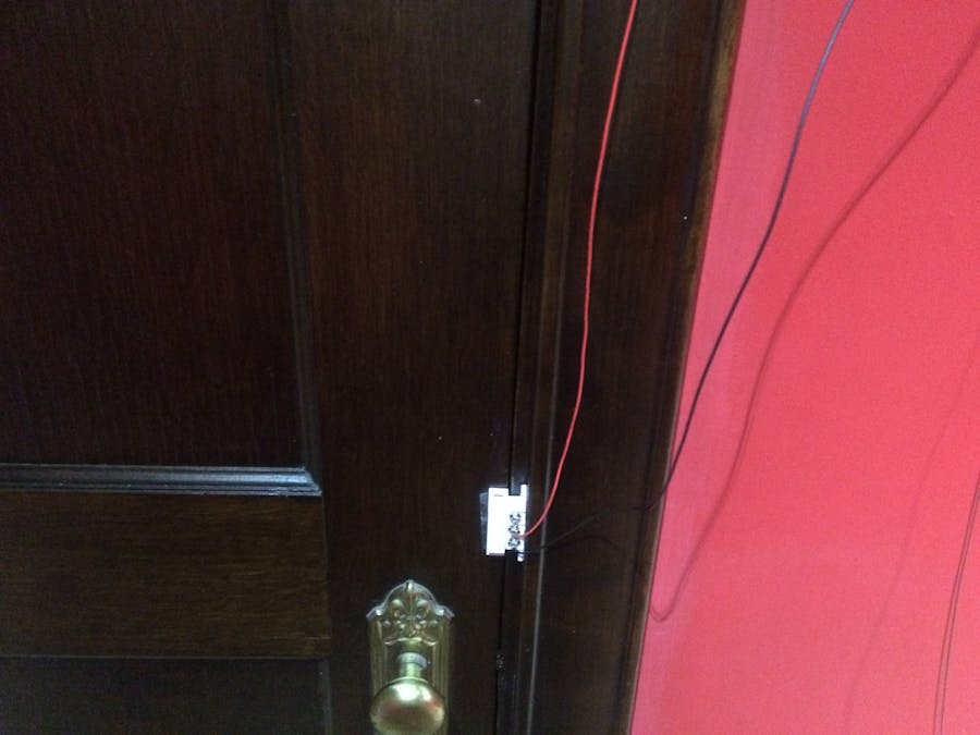
The magnet sensors are Reed switches. When near a magnet the internal connections change in comparison to their other "normal" state. They are classified as either N.C. or N.O. For Reed switches N.C. means "normally closed" and N.O. means "normally open". Again, "normally" refers to the state where they are not in contact with a magnet. On a switch that is only one of the two types this refers to the connection between the two pins If the switch can be either N.O. or N.C the label refers to the connection between that pad/pin etc. and the
Choose your configuration
Depending on your sensor number you will want to choose from one of multiple configurations. Read the descriptions and then decide which you will use.
A) Independent sensor nodes
Using independent sensor nodes is best for use with one or two sensors and has two upsides. The first is that the device can tell which specific sensor was activated, The second is that the switches can be normally off and therefore only go high when the sensor is activated. The downsides are that it commonly requires more total wire and requires a GPIO per sensor node.
B) Continual sensor network
Using a continual sensor is perfect for hooking up an unlimited number of sensor nodes without eating up GPIO space. In addition to this it also commonly uses less wire than a system with the same node positions using independent sensor nodes (depending on distance from sensors to the Edison). The downsides are that the whole network is set off when any node is and it requires a setup in which the signal is normally high.
Notes
**This section along with the code and schematics will refer to the independent sensor node setup as "A" or "Configuration A" and "B" or "Configuration B" for the continual sensor network.**
**Depending on your specific setup you may have to invert your sensor outputs to get the same results as I did. In my setup the magnet is normally touching the sensor, meaning connecting to N.O. would result in the sensor normally being closed and vice-versa. If your sensor and magnet are not normally touching do the opposite of what I say.**
**Figure out your sensor positions first. You will have to cut wire to length based on their positions.**
Shared Setup
No matter the configuration you choose the Edison needs a way to interface beyond the headers you already installed. These won't work because you would either have to solder the Edison to perfboard or use a breadboard which would cause shorts and damage. To solve this you can solder female headers to a perfboard.
On one side of your perfboard solder 4 rows 14 long of female headers. This is where you will plug the Edison in.
On the opposite side solder the same formation of male headers.
On the bottom of the board solder wires from the bottom of each female header to the corresponding male header.
The result is more or less a port for the Edison which can be connected to breadboards and other devices with the help of jumpers or plain old wire (and maybe heat shrink for insulation.
Setup (Configuration A)
For each sensor attach red wire to the COM. pin (stands for common) and black to N.C. Attach the red to 1.8v and the black to an unused normal GPIO pin.
Setup (Configuration B)
For each sensor attach red wire to the COM. pin (stands for common) and black to N.O. For each sensor attach the red wire to the black wire of the next sensor. At the end of this process one sensor will have an unconnected red wire on the sensor on the other end will have an unconnected black wire. Connect the red to 1.8v and black to an unused normal GPIO pin. If you want you can invert the signal going to the GPIO. Doing so will require you to change the code accordingly.
Project Complete!To finish up upload your code to the Edison and plug it into the battery pack.
What Just Happened?You've got your project setup, which is great, but what actually happens where the alarm is triggered? No lights flash. A buzzer doesn't sound. You don't receive and text. Not yet.
When the alarm is triggered the Edison updates the state of a thing shadow in the cloud. This thing shadow stores the state of the device. This is useful because other devices can retrieve the state of the shadow and respond accordingly. This means that you could connect another service to send a text, or another Edison could read the state and turn on an LED. Essentially you are saving the data to a variable which can be accessed by any device connected to AWS IoT.
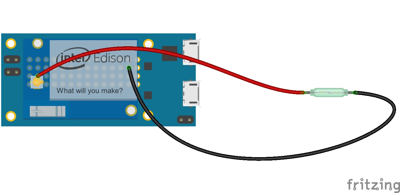
Single Node (Configuration A) Example
N.B. In Fritzing the pins are seemingly mislabeled. This diagram represents the proper physical arrangement, not the arrangement according to Fritzing's labels.
Node Network (Configuration B) Example
N.B. In Fritzing the pins on the Edison are seemingly mislabeled. This diagram represents the proper physical arrangement, not the arrangement according to Fritzing's labels.
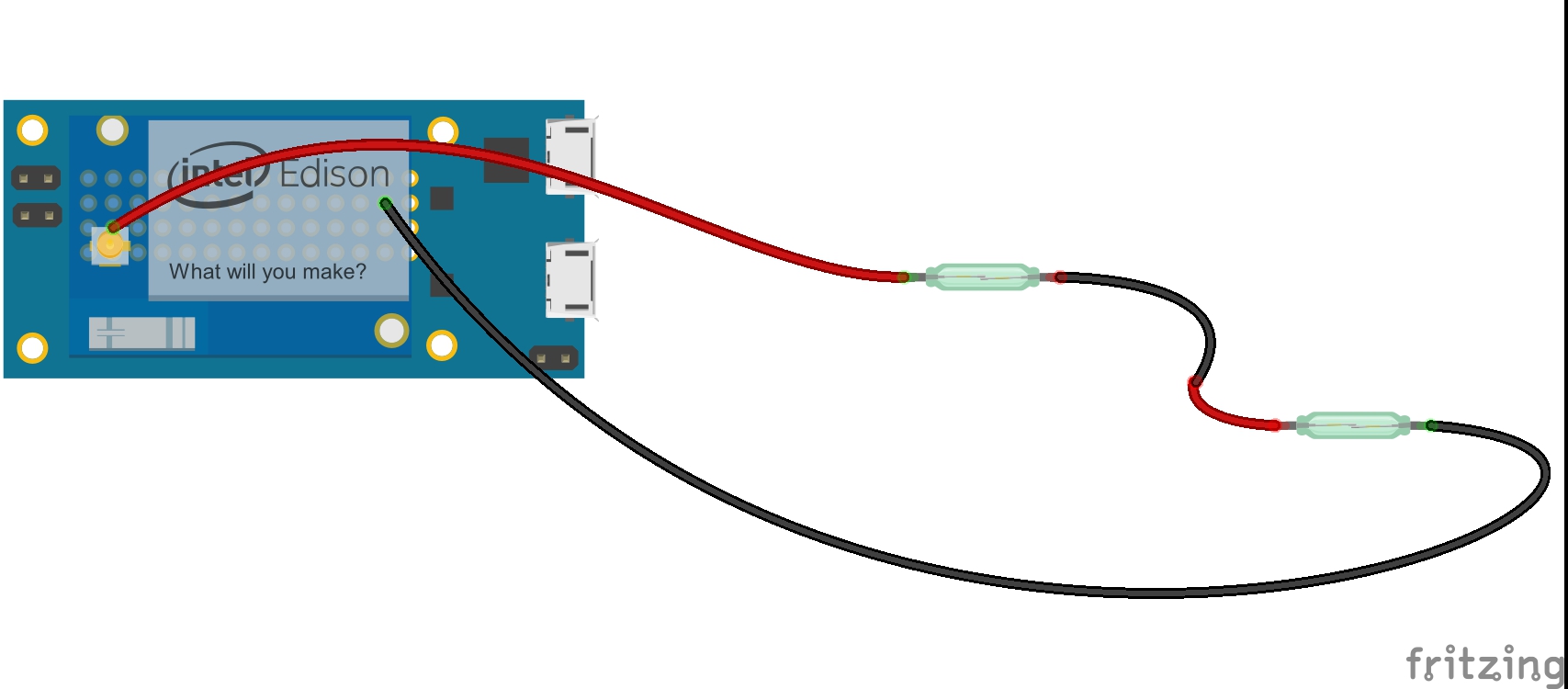
Node Network (Configuration B) Example
N.B. In Fritzing the pins are seemingly mislabeled. This diagram represents the proper physical arrangement, not the arrangement according to Fritzing's labels.

Comments