
Hardware components | ||||||
 |
| × | 1 | |||
| × | 1 | ||||
Software apps and online services | ||||||
| ||||||
When ever I get a new board, the first thing I want to do is figure out if I can turn it into a flight controller. Looking at the Kinetis boards, I saw they had great promise. A fast clock, plenty of RAM, expansive GPIO and the ability to communicate with a variety of sensors through different protocols with FlexIO. In addition to this, it has a built in accelerometer, which means there is one less sensor that needs to be added on.
Before I got ahead of myself and started working on autopilot, data transmission and sensor interfaces I started with the most simple and crucial part, motor control.
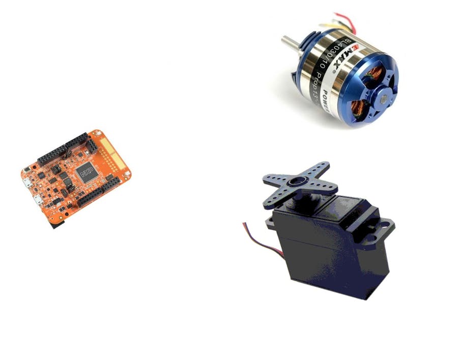
In quadcopters, tricopters and planes the two types of motors used are brushless motors (thrust) and servo motors (steering). Upon inspecting the SDK examples In noticed that there was (as I expected) not yet a servo or brushless motor driver. Luckily, they are controlled very similarly, and it is easy to add.
Servo BasicsBackground
Servo motors come in two forms, full rotation (rare) and more commonly limited rotation. This guide addresses limited rotation servos as full rotation servos aren't used for planes or tricopters.
A limited rotation servo (which I will just call a servo in the future) rotates through 180 degrees of positions and therefore can only perform half rotations. Servos are actually DC motors with a potentiometer attached to determine the point in rotation it is at. Servos are controlled with one data pin and powered through two others.
Interface
Servos are controlled through a form of Pulse Width Modulation. Ever 20ms the rising edge of a pulse begins meaning that it is a 50hz signal. The pulse length is what determines what position the servo moves to. The pulse typically ranges from 1-2ms, but different brands use different timing. Depending on where the length falls in this range the servo moves to a position. 1ms (the minimum) directs movement to 0 degrees. 2ms (the maximum) directs movement to 180 degrees. Following this pattern 1.5ms (half way) directs movement to 90 degrees.
What About Brushless?Luckily, this same method can be used to control brushless motors. While brushless motors themselves are controlled by three channels of AC current, the ESCs that create the pulses for them run digital. To simplify things ESCs are controlled like a servo, except before starting they require a low throttle (in the example above 1ms) to calibrate the range. This means the same code can be used, in fact on Arduino most firmware simply uses the Servo library.
Getting it Working on the Kinetis BoardAs I said previously, the Kinetis board does not have a Servo library, so I had to make my own (lite) version of one. The first option I considered was performing a port of the Arduino Servo or SoftwareServo libraries. Upon inspection I noticed that all I had to change was the use of the Arduino native timers and adjust some calculations for the new clock rate. At first this seemed like a good choice, but both libraries were somewhat cryptically written at times and SoftwareServo is said to have low resolution which could lead to quad instability.
This mean the obvious option was to make a new library from scratch. Afterall, it isn't that complicated. Still, due to the versitailty of the board there were seemingly half-a-dozen ways to go about doing this. I could use the FTM/PWM, configure the FlexIO to create a pulse or just use NOP delay for timing.
Due to my familiarity with the platform I decided to go with NOP because I had done it before. The NOP instruction tells the CPU to wait one clock cycle before performing the next operation. This makes it a simple and effective way to create a delay.
What the code ends up doing is calculating on times and off times so that the rising edge of a pulse will occur ever 20ms and end 1-2ms later depending on the desired position. Then waiting continues until 20ms since the start of the rising edge and another pulse begins.
Wrap Up and Going ForwardTo download code to your board follow these instructions to set up the Kinetis Design Studio IDE and proper debugging tools.
As can be seen, this is just an introductory project and there is much more to be done. As the topic matter would suggest I am working on using the board as the flight controller of a quad, but am not ready to fly or document it yet. I only wrote this up because the deadline for the trip to Austin and the fact that there were not many complete entries. I plan to continue working on this until I have finished the quad and work on using FlexIO instead of my current method, but due to the lack of time I did what I could. I hope this is helpful to anyone wanting to do something similar.Lastly, I would like to thank NXP and Hackster for putting together this contest and all the great documentation they have for the board. While there is definitely a learning curve I gained more knowledge on the lower level workings of microcontrollers from even this simple project that anything else I have done before. The SDK was a great place to get started and was able to give me the boost I needed (I'm sad to say I am almost completely clueless when it comes to C as I am used to using C# now and always start using the wrong syntax and keywords). As far as anyone else working on a project I really do suggest the Webinars (old and new) and the getting started guides on NXPs website. If you are really invested I suggest the complete documentation found here, which I've read a few hundred relevant pages of (sections on timers, PWM and FlexIO) and have gained an overwhelming amount of knowledge from.
Comments