

Hardware components | ||||||
| × | 1 | ||||
| × | 1 | ||||
| × | 1 | ||||
Software apps and online services | ||||||
 |
| |||||
| ||||||
 |
| |||||
Hand tools and fabrication machines | ||||||
 |
| |||||
 |
| |||||
 |
| |||||
 |
| |||||
Lighting has always been a way to create mood, style, and energy in our rooms. But why settle for a simple lamp when you can build your own 3D-printed multipurpose smart light box?
I recently developed a 3D Printed Smart LED Box powered by WS2812 LEDs (8×16 panel) and ESP8266, which works as:
- 🎶 VU Meter (music reactive light)
- 🌈 Color Shade Controller
- 💡 Brightness Adjustable Room Theme Light
- 🎉 Party Mode Light
And much more!
With 3D printing + electronics, the possibilities are endless. Let’s walk through the build step by step.
🧰 Components RequiredHere’s the complete parts list for this project:
3D Printed Parts- 🖤 Base Part
- ⚪ Diffuser Part (white, for smooth lighting effect)
- WS2812 8×16 LED Panel
- ESP8266 Wi-Fi board
- TP4056 charging module
- 2S Li-ion battery pack (3S also supported)
- 3 × Tactile push buttons
- 1 × Power rocker switch
- Screws + Screwdriver
- Start with the 3D-printed base part. This base has pre-designed slots where each electronic component fits securely.
- Insert the ESP8266 module into its dedicated slot. Make sure it sits tightly, as this is the brain of the whole project.
- Next, take the power rocker switch and push it gently into the switch slot on the base. This will allow you to power the box ON/OFF easily.🛠️ Step-by-Step Assembly
- For powering the LED matrix, we need a rechargeable battery. I used a 2S battery configuration (7.4V), but you can also go with a 3S battery (11.1V) depending on availability.
- Place the battery into the battery slot on the base.
- Make sure the wires are accessible for later connection.
Keep in mind that battery placement should be neat and not block other slots.
- To recharge the battery easily, we’ll use a TP4056 charging board.
- First, solder the Battery + wire → TP4056 B+ pad.
- Then, solder the Battery – wire → TP4056 B- pad.
- Once soldered, fix the TP4056 board into its dedicated slot in the base.
- This module will allow safe charging through a micro-USB port.
Now, let’s add the user controls. Our design includes 3 tactile push buttons that will be used to:
- Change LED colors 🌈
- Switch between lighting patterns 🔄
- Adjust brightness 🔆
Insert each push button into its slot in the base.
Ensure the buttons are oriented properly so they click easily when pressed from the outside.
These buttons will later connect to the ESP8266 for input control.
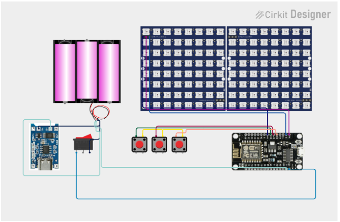
This is where all the components come together. Use the provided circuit diagram
Connect ESP8266 output pins → WS2812 input (DIN, GND, VCC).
Wire the tactile buttons → ESP8266 GPIO pins for control inputs.
Ensure the battery + switch → ESP8266 power input is properly linked.
Double-check polarity (especially on the battery) to avoid damage.
Now comes the software part.
- Connect the ESP8266 to your computer using a USB cable.
- Open Arduino IDE (or PlatformIO).
- Install the FastLED or Adafruit NeoPixel library.
- Select NodeMCU / ESP8266 as the board type.
- Load the provided sketch https://github.com/souravmahari/DIY-3D-Printed-Smart-LED-Box-using-WS2812-8-32-ESP8266-/tree/main
- Click Upload.
After uploading, the ESP8266 will start running the programmed LED patterns
📂 Download 3D Print FilesThis project uses two 3D-printed parts:
🖤 Base Part – to hold ESP8266, switches, battery, and LED panel
⚪ Diffuser Part – for smooth light diffusion
📦 Looking for the STL files?Drop me a quick DM and I’ll send you the download link right away! or click here
🖨️ Don’t have a 3D printer? No worries — you can easily get your parts printed through JUSTWAY.
JUSTWAY offers a full range of 3D printing technologies — SLA, SLS, DLP, MJF, FDM, and SLM — and supports a wide selection of materials including resin, nylon, PLA, ABS, PETG, TPU, PC, ASA, PEEK, aluminum, stainless steel, and titanium.
⚙️ They’re your trusted partner for custom 3D printing and CNC machining. Whether you’re prototyping functional parts, building custom enclosures, or creating unique designs, JUSTWAY delivers fast turnaround and exceptional quality every time.
👉 Ready to bring your idea to life? Click here for an instant quote.
⚠️ Printing Tip:
Print the base in black PLA/ABS for strength and neat finish.
Step 7: Installing the LED Panel ✨Now it’s time to place the 8×32 WS2812 LED panel into the box. But before directly fixing it into the slot, there’s one important step to make the wiring easier:
Take female jumper wires (3 wires: VCC, GND, and DATA).
Solder them carefully to the input pads of the WS2812 panel (DIN, +5V, GND).
These female jumpers will later plug into the corresponding male header pins connected to the ESP8266 (as per the circuit diagram).
Double-check the polarity while soldering — red for VCC, black for GND, yellow/green for Data (or use your own consistent color code).
Once the jumpers are soldered and secured, gently place the LED panel into the 3D-printed base slot.
Ensure that the jumper wires are routed neatly to avoid bending or damage.
Finally, place the white diffuser part on top of the LED panel.
This diffuser spreads the light evenly across the surface, giving the box a premium and professional look.
Without the diffuser, the LEDs look harsh, but with it, the box glows smoothly.
Flip the power switch and watch your creation light up! You can now:
- Switch between different color shades
- Adjust brightness levels
- Enjoy VU Meter mode for music
- 🎶 Music VU Meter – LEDs dance to the beat.
- 🌈 Room Ambience – Create calming or vibrant environments.
- 💡 Theme Lighting – Match your room mood.
- 🎉 Party Lighting – Turn your room into a disco zone.
This project has plenty of upgrade potential:
- 📶 Add Wi-Fi Control via mobile/web app
- 🎙️ Connect with Alexa or Google Home for voice control
- 📱 Build a custom smartphone app for pattern selection
- 🔋 Improve battery management for longer runtime
This DIY project proves how 3D printing and electronics can come together to create something useful, fun, and stylish. The Smart LED Box is not just a lamp — it’s a multipurpose light gadget that you can customize endlessly.

_t9PF3orMPd.png?auto=compress%2Cformat&w=40&h=40&fit=fillmax&bg=fff&dpr=2)


Comments