


Hardware components | ||||||
| × | 1 | ||||
| × | 1 | ||||
 |
| × | 1 | |||
| × | 1 | ||||
| × | 1 | ||||
Software apps and online services | ||||||
 |
| |||||
_4YUDWziWQ8.png?auto=compress%2Cformat&w=48&h=48&fit=fill&bg=ffffff) |
| |||||
| ||||||
| ||||||
Hand tools and fabrication machines | ||||||
 |
| |||||
 |
| |||||
Watch the full video here - https://youtu.be/onVQNZKV-7c
IntroductionRechargeable batteries are an essential part of modern DIY electronics, robotics projects, and embedded systems. Managing and charging multiple batteries safely and efficiently can quickly become a challenge for makers and engineers.
Almost two years ago, I built a simple battery charging station using TP4056 modules, and the response from the maker community was overwhelming. More importantly, that charging station has been running reliably ever since. With evolving project needs and better design ideas, it was time for a complete redesign.
In this article, I present a 10-cell battery charging station designed specifically for 18650 Li-ion batteries, featuring TP4056 charging modules, Type-C and Micro-USB support, XT60 high-current input, and real-time voltage and current monitoring. This project is ideal for DIY electronics enthusiasts, Hackster readers, and Instructables makers looking for a scalable, safe, and professional battery charging solution.
Project Highlights- Charges up to 10 × 18650 Li-ion batteries simultaneously
- Based on TP4056 Li-ion charging modules
- Supports Type-C and Micro-USB charging inputs
- Individual ON/OFF control per charging channel
- XT60 connector and screw terminal for high-current 5V input
- Supports mini Li-Po battery charging
- Built-in voltmeter for real-time battery voltage monitoring
- Volt-amp meter for total current and power consumption
- Compact & modular PCB design
The charging station is built around multiple independent TP4056 linear charging circuits, each dedicated to a single battery cell. This modular approach ensures safe, controlled charging and makes the system easy to expand or troubleshoot.
Power is supplied through a common 5V rail and distributed to each charging channel via individual switches. Monitoring modules provide real-time feedback on voltage, current, and total power consumption.
How It WorksEach charging channel in this project operates independently using a TP4056 Li-ion charging module. The TP4056 is a popular constant-current / constant-voltage (CC/CV) charger designed specifically for single-cell lithium batteries.
Charging Process- Power InputA regulated 5V supply is fed into the system via either an XT60 connector or screw terminals. This 5V rail powers all TP4056 modules simultaneously.
- Channel ControlEach TP4056 module is connected through an individual SPST/VTR switch, allowing users to enable or disable charging for any specific battery slot.
- Battery ChargingWhen a battery is inserted:
- The TP4056 starts charging in constant current mod
- As the battery approaches 4.2V, it switches to constant voltage mode
- Charging automatically terminates when the current drops below the cutoff threshold
- Monitoring & Feedback
- A voltmeter displays real-time battery voltage
- A volt-amp meter measures total system current and power consumption
- Mini Li-Po Support Selected TP4056 channels are routed to a JST connector, allowing safe charging of mini Li-Po batteries using the same CC/CV charging principle.
This architecture ensures safe charging, flexibility, and scalability while keeping the design simple and reliable.
Components RequiredCore Components- TP4056 Charging Modules (Type‑C & Micro‑USB variants) x 10
- 18650 SMD Battery Holders × 10
- Custom PCB x 1
- SPST / VTR Switches × 10
- 10‑Pin DIP Switch x 1
- XT60 Male & Female Connectors x 1 each
- 2‑Pin Screw Terminals x 2
- 2‑Pin JST Connector (for mini Li‑Po) x 2
- Voltmeter Module x 1
- Volt‑Amp Meter Module x 1
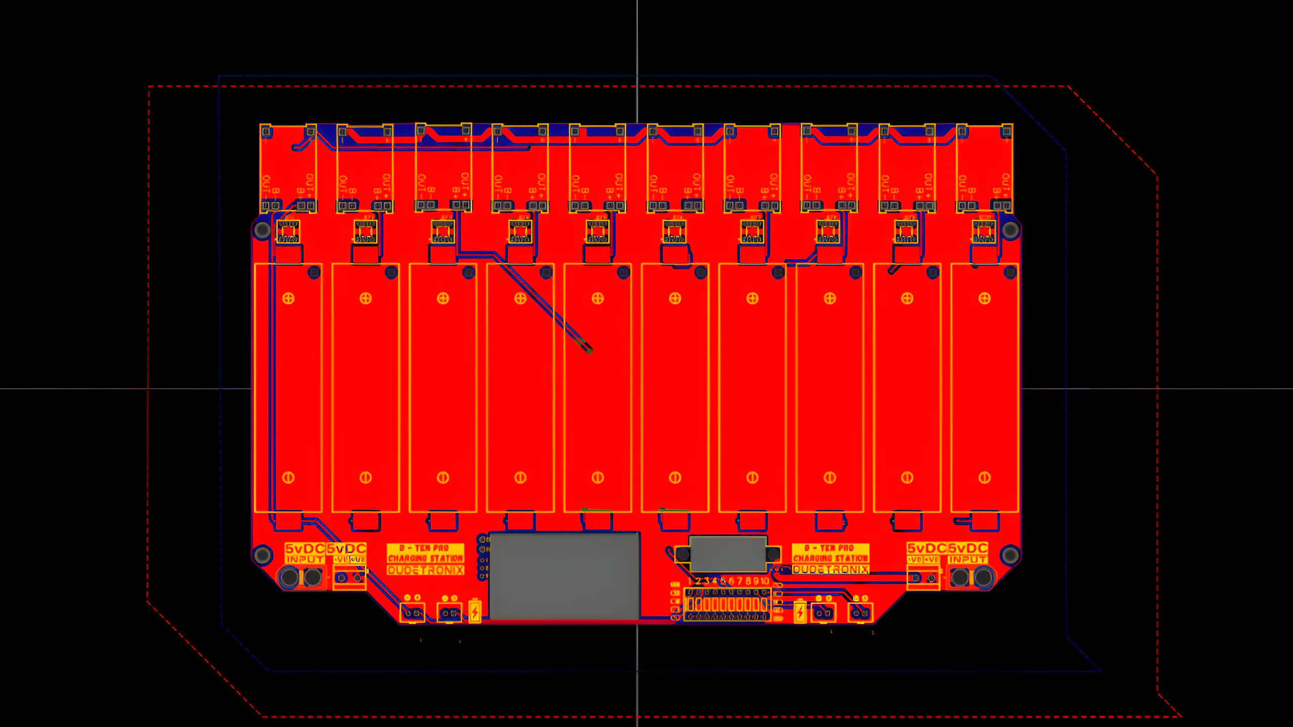
The PCB was designed from scratch with a strong focus on:
- Clean routing and current handlin
- Proper spacing for battery holders
- Accurate cutouts for meters
- Easy assembly and maintenance
Compared to the previous version, the PCB layout and appearance are completely redesigned, resulting in a more professional and robust charging station.
After finalizing the design, Gerber files were generated and sent for fabrication.
Start by placing the TP4056 charging modules onto the PCB. Both Type‑C and Micro‑USB variants are used.
Carefully solder each module, ensuring:
- Proper pad alignment
- Strong solder joints
⚠️ Weak solder joints can break if the PCB flexes, causing charging failures.
2. Installing the 18650 Battery HoldersNext, solder the SMD 18650 battery holders.
These holders were chosen because:
- Batteries can be inserted and removed easily
- They provide a cleaner look
- They are more convenient than traditional through‑hole holders
To control each charging channel independently, SPST/VTR switches are added.
This allows:
- Individual ON/OFF control
- Selective charging of batteries
- Reduced unnecessary power usage
Once positioned, solder all switches securely.
Now add and solder the following connectors:
- 10‑Pin DIP Switch
- 2‑Pin Screw Terminals
- XT60 Male & Female Connectors
- 2‑Pin JST Connector (Mini Li‑Po charging)
Ensure all connectors are soldered properly to handle current safely.
5. Voltmeter & Volt‑Amp Meter InstallationInsert the volt‑amp meter into its PCB cutout, followed by the voltmeter.
Then:
- Connect and solder the volt‑amp meter wires
- Connect and solder the voltmeter wires
These meters provide:
- Real‑time system voltage
- Total current draw
- Overall power consumption
For now, a second PCB is used as the back cover.
Using M3 brass spacers and M3 bolts, the back PCB is mounted securely.
A custom 3D‑printable back cover has also been designed and can be used for a more polished enclosure.
After designing the enclosure, it’s time to print it. I will be using my 3D printer, and the entire model will be printed in PLA for ease and reliability. Once printing is complete, the enclosure will look like this. I have also added M3 brass inserts to securely mount the PCB inside.
You can download the STL file and print it on your own 3D printer. If you don’t have access to a 3D printer, don’t worry—you can use an online 3D printing service that will print and ship it to you. Click here to order through a reliable service.
ABS is a common thermoplastic with good mechanical properties and excellent impact strength. Compared to PLA, ABS offers higher toughness and better heat resistance, making it suitable for functional prototypes and end-use parts, although with slightly less fine detail resolution.
ABS is widely used in applications that require durability, dimensional stability, and resistance to impact and heat.
Process Compatibility
- FDM (Fused Deposition Modeling)
Available ColorsWhite, Black, Silver Gray, Red, Blue, Yellow, Green
Material AdvantagesABS has good impact resistance and heat resistance, as well as low-temperature resistance, chemical resistance, and excellent electrical properties. It is easy to process, offers stable dimensional accuracy, and provides good surface gloss.
Material LimitationsThe bending strength and compressive strength are relatively low, and the mechanical properties are significantly affected by temperature.
Post-Processing & Secondary FinishingABS is easy to paint and color and supports secondary surface processing such as metal spraying, electroplating, welding, hot pressing, and adhesive bonding.
Common Applications
- Automotive applications
- Instrument panels
- Pillar trim
- Door liners and handles
High-Performance Plastic 3D Printing
Justway offers a full range of high-performance plastic materials for industrial and functional 3D printing, including photosensitive resins, general-purpose thermoplastics, engineering-grade plastics, and high-temperature super engineering plastics.
Available Materials:
- Resin – High-detail, smooth surface finishes
- Nylon (PA) – Durable and flexible for functional prototypes
- PLA – Easy-to-print, eco-friendly, versatile
- ABS – Impact-resistant and heat-tolerant
- PETG – Strong, chemical-resistant, weatherable
- TPU – Flexible and elastic for soft-touch part
- PC (Polycarbonate) – High strength and heat resistance
- ASA – UV-resistant and weatherable for outdoor applications
- PEEK & PPS – High-temperature, chemically resistant engineering plastics
With Justway, you can quickly produce custom 3D printed parts in ABS or other advanced plastics, with reliable quality and fast turnaround. Click here to order your 3D printed parts today and bring your designs to life.
Power Input OptionsThe charging station can be powered using:
- XT60 Connector (recommended)
- Screw Terminals
⚠️ Always supply 5V only. Higher voltage will damage the TP4056 modules.
Power Supply Recommendation
- Minimum: 5V, 10A
- Lower current supplies will increase charging time
Before charging, each battery’s voltage is checked:
- Example readings: 3.5V – 4.1V
After connecting the 5V power supply via XT60:
- Charging begins immediately
- Individual channels can be enabled or disabled
Charging Notes
- Type‑C / Micro‑USB input: 1–4 cells max
- XT60 / Screw terminal input: Up to 10 cells
After approximately 3–4 hours, all batteries reach full charge.
The charging station also supports mini Li‑Po batteries.
- Use the first or last two TP4056 channels
- Connect via the JST connector
This adds extra flexibility compared to the previous version.
Safety Notes- Use only protected 18650 cells when possible
- Ensure adequate ventilation
- Do not exceed 5V input
- Use a stable and regulated power supply
This 10-cell TP4056-based battery charging station is a powerful upgrade over the original design. With support for multiple 18650 Li-ion cells, mini Li-Po batteries, Type-C and Micro-USB charging, and XT60 high-current input, it provides a reliable and scalable solution for any electronics workbench.
The redesigned PCB, individual channel control, and real-time monitoring make this project suitable for DIY electronics, robotics, IoT prototyping, and battery testing applications. Whether you are a beginner maker or an experienced engineer, this charging station can significantly improve your workflow.
If you have ideas for additional features or future upgrades, feel free to share them. Continuous improvement is what makes open-source hardware projects truly powerful.

_t9PF3orMPd.png?auto=compress%2Cformat&w=40&h=40&fit=fillmax&bg=fff&dpr=2)

_Ujn5WoVOOu.png?auto=compress%2Cformat&w=40&h=40&fit=fillmax&bg=fff&dpr=2)
Comments