
The Pico is the brains. It reads GPS coordinates from the Neo-6M and then shoots them off to the cloud through the SIM800L module using simple HTTP requests.
On the server side, we’re using Circuit Digest’s GeoLinker API. Once you register and get an API key, your Pico can log data to the cloud, and you’ll see your route show up on a live map.
And here’s the nice bonus: if the GSM signal drops, the Pico buffers your location points locally. Once it reconnects, it pushes the backlog first, then continues streaming live updates. No data loss, even in patchy coverage areas.
Understanding the ModulesSIM800L GSM/GPRS Modules
This tiny board handles voice, SMS, and GPRS data over 2G networks (quad-band, so 850, 900, 1800, and 1900 MHz). It talks to the Pico over UART and is controlled with good old AT commands.
Cool features you get:
- Voice calls, SMS, and internet through GPRS
- TCP/UDP and HTTP support, which is what we use here
- Sleep and idle modes for low power use
- Network scanning and signal quality reports
Hardware notes:
- Needs 3.7V to 4.2V and up to 2A current
- Needs an external GSM antenna
- Uses 2.8–3V logic, but works fine with Pico’s 3.3V pins
Neo-6M GPS Module
This little guy is from u-blox and is one of the cheapest GPS modules around. It only talks to GPS satellites (not GLONASS, Galileo, etc.), but it’s accurate and reliable enough for most DIY and Raspberry Pi Pico projects.
Highlights:
- Speaks NMEA 0183 sentences like $GPGGA and $GPRMC at 9600 bps
- Tracks weak signals down to -161 dBm
- Position accuracy of about 2.5 meters in good conditions
- TTFF (time-to-first-fix) as fast as 1 second (hot start)
- Runs on 3.3V and draws around 50 mA
- Status LED blinks when it gets a fix
You’ll definitely want to pair it with a proper GPS antenna for faster locks.
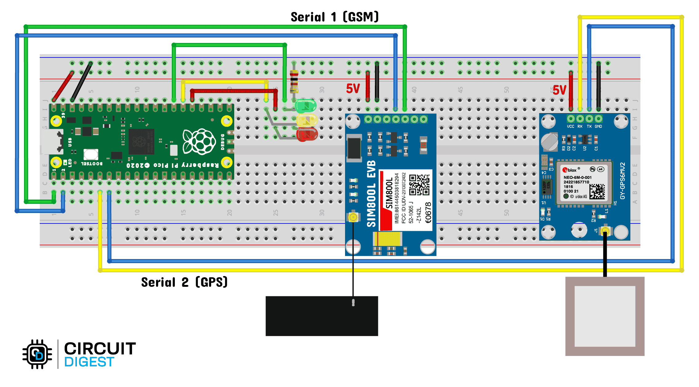
Wiring GuideHere’s the gist of the connections:
SIM800L to Pico
- TX → GP1 (RX)
- RX → GP0 (TX)
- GND → GND
- VCC → 3.7–4.2V external supply
Neo-6M to Pico
- TX → GP5 (RX)
- RX → GP4 (TX)
- GND → GND
- VCC → 3.6V supply (or Pico 5V if your module has an onboard regulator)
Important: make sure all three modules share a common ground.
Setting Up CircuitDigest Cloud (GeoLinker)CircuitDigest Cloud is the backend we’re using to visualize data. Once you sign up at circuitdigest.cloud
, you can generate an API key from your account dashboard.
That key is what authenticates your Pico with the GeoLinker API. The free plan lets you log up to 10, 000 GPS points per key. Once you hit the cap, you just generate a new one.
Arduino IDE SetupWe’ll program the Pico using Arduino IDE. Here’s the quick setup:
- Open Arduino IDE and go to File > Preferences.
- In “Additional Board Manager URLs, ” paste:
https://github.com/earlephilhower/arduinopico/releases/download/global/package_rp2040_index.json- Go to Tools > Board > Boards Manager and install “Raspberry Pi Pico / RP2040 by Earle Philhower.”
- Next, go to Tools > Manage Libraries and search for “GeoLinker.” Install it.
- After that, you’ll see examples under File > Examples > GeoLinker.
That’s it, the IDE is ready.
Common Troubleshooting- GeoLinker library not showing up? Restart Arduino IDE after installing it. Also make sure the folder name is exactly GeoLinker.
- Board not detected? Double-check you’ve selected Raspberry Pi Pico or Pico W in Tools > Board.
- SIM800L not responding? Nine out of ten times it’s power. Check your supply and current rating.
The complete code we used is available in the code section. It handles GPS reading, HTTP upload, and offline buffering.
Upload it, plug in your SIM, and you’re good.
Code Snippet:
#include <GeoLinker.h>

// GPS SERIAL CONFIGURATION
#define gpsSerial Serial2  // UART1
#define GPS_RX 4
#define GPS_TX 5
#define GPS_BAUD 9600

// GSM SERIAL CONFIGURATION
#define gsmSerial Serial1  // UART0
#define GSM_RX 0
#define GSM_TX 1
#define GSM_BAUD 9600

// LED DEFINITIONS
#define LED_GREEN 21
#define LED_YELLOW 20
#define LED_RED 19

// GeoLinker setup
const char* apiKey = "your_api_key";
const char* deviceID = "GeoLinker_tracker_test1";
GeoLinker geo;

void setup() {
  Serial.begin(115200);

  // GPS UART
  gpsSerial.setTX(GPS_RX);
  gpsSerial.setRX(GPS_TX);
  gpsSerial.begin(GPS_BAUD);

  // GSM UART
  gsmSerial.setTX(GSM_RX);
  gsmSerial.setRX(GSM_TX);
  gsmSerial.begin(GSM_BAUD);

  // LEDs
  pinMode(LED_GREEN, OUTPUT);
  pinMode(LED_YELLOW, OUTPUT);
  pinMode(LED_RED, OUTPUT);

  // GeoLinker Init
  geo.begin(Serial2);
  geo.setApiKey(apiKey);
  geo.setDeviceID(deviceID);
  geo.setUpdateInterval_seconds(3);
  geo.setNetworkMode(GEOLINKER_CELLULAR);
  geo.setModemCredentials("gprs", nullptr, nullptr);
  geo.beginModem(Serial1);

  Serial.println("GeoLinker setup complete.");
}

void loop() {
  geo.setPayloads({
    {"temperature", 27.5},
    {"humidity", 65.3}
  });
  geo.setBatteryLevel(90);

  uint8_t status = geo.loop();
  if (status == STATUS_SENT) {
    Serial.println("Data sent successfully!");
    digitalWrite(LED_GREEN, HIGH);
    delay(500);
    digitalWrite(LED_GREEN, LOW);
  }
}Once everything’s wired and programmed:
- Power up the Pico.
- Wait for the GPS to lock (status LED will blink).
- Watch the serial monitor for logs.
- Log into CircuitDigest Cloud with your API key, and you’ll see your points show up on the map.
Take it for a spin in your car or bike and watch your route plot in real time.
This project guide is based on: Raspberry Pi Pico GPS Tracker

Comments