


Hardware components | ||||||
_ztBMuBhMHo.jpg?auto=compress%2Cformat&w=48&h=48&fit=fill&bg=ffffff) |
| × | 1 | |||
 |
| × | 1 | |||
 |
| × | 1 | |||
 |
| × | 1 | |||
Software apps and online services | ||||||
 |
| |||||
Hand tools and fabrication machines | ||||||
 |
| |||||
This project demonstrates how to build an intelligent dual-axis solar tracking system that automatically adjusts a solar panel's position to follow the sun throughout the day. By monitoring light intensity from multiple directions using LDR sensors, the system controls two servo motors to maintain optimal panel alignment, significantly improving energy capture compared to fixed installations.
The tracker operates along both horizontal (azimuth) and vertical (elevation) axes, enabling it to compensate for the sun's movement across the sky from sunrise to sunset, as well as seasonal variations in solar altitude. This continuous alignment can increase energy output by 30-40% compared to stationary panels.
Four LDR (light-dependent resistor) sensors are positioned at the corners of the solar panel in a cross formation - top-left, top-right, bottom-left, and bottom-right. Each LDR forms a voltage divider circuit with a 10kΩ resistor, allowing the Arduino to read analog light intensity values.
The Arduino continuously samples all four sensors and calculates average light levels for the top, bottom, left, and right sides of the panel. When it detects a significant difference in light intensity between opposing sides (exceeding a predefined tolerance threshold), it commands the appropriate servo motor to rotate the panel toward the brighter direction.
The horizontal servo controls east-west positioning, while the vertical servo adjusts the north-south tilt. This dual-axis control ensures the panel remains perpendicular to incoming sunlight throughout the day. When ambient light drops below a certain threshold (such as during nighttime), the system enters standby mode to conserve energy and prevent unnecessary servo movement.
Key Features- Automatic sun tracking along both horizontal and vertical axes
- Real-time light sensing using four LDR sensors in a cross configuration
- Intelligent positioning through an averaging algorithm to reduce noise
- Energy-efficient standby mode during low-light conditions
- 30-40% energy gain over fixed solar panel installations
- Modular 3D-printed mechanical structure for easy assembly
- Simple Arduino programming with clear, commented code
Hardware:
- Arduino UNO (1)
- LDR sensors, 5mm (4)
- Micro servo motors (2)
- Solar panel (1)
- 10kΩ resistors (4)
- Breadboard (1)
- Jumper wires (as needed)
- 3D-printed mounting structure
Software:
- Arduino IDE
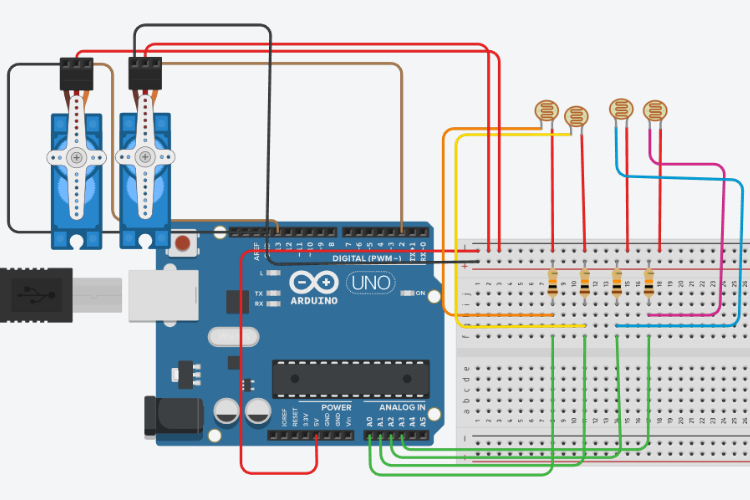
The circuit architecture centres around the Arduino UNO microcontroller:
LDR Sensor Connections:
- Top-Left LDR → Arduino A0
- Top-Right LDR → Arduino A3
- Bottom-Left LDR → Arduino A1
- Bottom-Right LDR → Arduino A2
Each LDR connects to 5V through a 10kΩ resistor (voltage divider configuration), with the junction point connected to the respective analog input pin.
Servo Motor Connections:
- Horizontal Servo (left-right movement) → Arduino Digital Pin 2
- Vertical Servo (up-down movement) → Arduino Digital Pin 13
- Both servos connect to 5V power and a common ground
Important: Servo motors typically require more current than the Arduino can safely provide. Use an external 5V power supply for the servos to prevent damage to the Arduino board.
All mechanical components for this build were 3D-printed, ensuring precise alignment and stable movement. The design includes:
- Base platform - provides stable mounting for the entire assembly
- Horizontal servo mount - allows rotation along the azimuth axis
- Vertical servo mount - enables tilt adjustment along the elevation axis
- Solar panel bracket - securely holds the panel while allowing movement
- LDR sensor housing - positions sensors in a cross formation around the panel
The 3D models used in this project ensure that the servo motors can rotate smoothly without mechanical interference and that the LDRs are positioned to accurately detect directional light differences.
The Arduino sketch implements an intelligent tracking algorithm:
Sensor Reading with Averaging: The readAverage() function samples each LDR sensor 10 times and returns the average value, effectively filtering out random noise and fluctuations that could cause erratic servo movement.
Light Difference Calculation: The code computes average light intensity for each side of the panel by averaging adjacent sensor readings:
- Top average = (top-left + top-right) / 2
- Bottom average = (bottom-left + bottom-right) / 2
- Left average = (top-left + bottom-left) / 2
- Right average = (top-right + bottom-right) / 2
Servo Adjustment Logic: The system calculates the vertical difference (top vs. bottom) and the horizontal difference (left vs. right). If either difference exceeds the tolerance threshold, the corresponding servo adjusts by a small increment in the direction of higher light intensity.
Night Mode: When the average of all four sensors drops below 200 (configurable threshold), the system recognises low-light conditions and pauses tracking operations, preventing unnecessary movement and conserving power.
Movement Limits: The code includes software limits to prevent the servos from rotating beyond their physical range, protecting the mechanical assembly from damage.
Real-World PerformanceTesting demonstrates that the system responds instantly to changes in light direction. When a light source moves left, right, up, or down, the tracker adjusts the panel's position within seconds to maintain optimal alignment.
The dual-axis capability provides significant advantages:
- Morning/evening efficiency: Captures low-angle sunlight that fixed panels miss
- Seasonal adaptation: Automatically adjusts for changing solar altitude throughout the year
- Cloudy day performance: Tracks diffuse sunlight when directional differences exist
- 30-40% energy gain: Substantially increases daily energy harvest compared to fixed installations
This solar tracking system is ideal for:
- Remote monitoring stations requiring maximum solar efficiency
- Educational demonstrations of renewable energy concepts
- DIY solar power installations in areas with limited panel space
- Research projects studying solar panel positioning optimisation
- Off-grid power systems where every watt counts
Fixed Mount:
- Energy gain: 0% (baseline)
- No tracking capability
- Lowest complexity
- Manual seasonal adjustment required
Single-Axis Tracker:
- Energy gain: 20-25%
- Tracks along one axis (typically east-west)
- Medium complexity
- Manual seasonal adjustment is still needed
Dual-Axis Tracker (This Project):
- Energy gain: 30-40%
- Tracks along both axes automatically
- Higher complexity but better performance
- Automatic seasonal adjustment
- Superior morning/evening efficiency
Possible improvements to this design include:
- GPS module integration for astronomical tracking algorithms
- WiFi connectivity for remote monitoring and control
- Battery voltage monitoring for power management
- Weather-resistant enclosure for outdoor deployment
- Larger servo motors for supporting bigger solar panels
- Data logging for performance analysis
This dual-axis solar tracking system using Arduino demonstrates how affordable components and smart algorithms can dramatically improve solar panel efficiency. The Arduino-based controller, combined with simple LDR sensors and servo motors, creates an intelligent system that maximises energy capture throughout the day and across seasons.
The project is accessible to makers with basic electronics knowledge while providing substantial practical benefits. Whether you're building an off-grid power system, creating an educational demonstration, or simply exploring renewable energy technology, this solar tracker offers an excellent balance of performance, complexity, and cost.


Comments