


Hardware components | ||||||
 |
| × | 1 | |||
| × | 1 | ||||
| × | 1 | ||||
| × | 1 | ||||
| × | 1 | ||||
 |
| × | 1 | |||
 |
| × | 1 | |||
 |
| × | 1 | |||
Software apps and online services | ||||||
| ||||||
Hand tools and fabrication machines | ||||||
 |
| |||||
| ||||||
 |
| |||||
| ||||||
While attending an IT conference, I noticed some colleagues wearing commercial, Chinese-made Bluetooth LED badges. I thought it was a brilliant concept—far more practical and dynamic than traditional paper badges. I immediately wanted one for myself.
However, after examining these off-the-shelf LED badges, several limitations became apparent:
- Single Color: The color is hardcoded into the hardware and cannot be changed.
- Low Resolution: The 11x44 pixel matrix severely restricts the amount of information you can display.
- No Battery Monitoring: There is no way to track the remaining battery percentage or state.
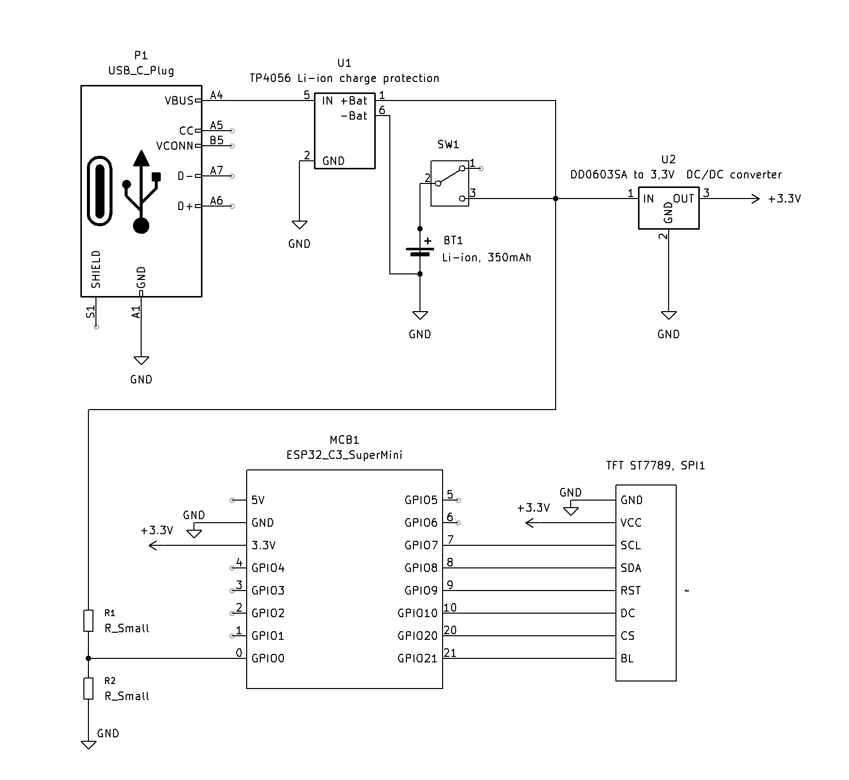
More importantly, buying a factory-made badge felt like a missed opportunity when I could build one myself. I dug into my microcontrollers box and pulled out an ESP32-C3_SuperMini, which features built-in Wi-Fi. This tiny but incredibly capable device was perfect: it could host a local server for configuration and then enter a low-power sleep mode, waking up periodically to monitor the battery.
From there, I designed the system step-by-step, prioritizing cost-effective yet feature-rich components. An e-ink display would have been the ideal choice for power efficiency, but I did not have one on hand. Instead, I ordered a 2.25-inch TFT LCD (76x284 pixels), which arrived quickly and cost three times less.
The rest of the hardware came together from spare parts:
- A defunct Bluetooth headphone case donated its 400 mAh Li-Po battery.
- A TP4056 charge controller module
- A DC/DC 3.3V buck/boost converter.
- Some resistors.
Building this device during my free evenings provided an unmatched sense of development satisfaction.
Getting the Wi-Fi and the basic web server running was standard procedure.
However, getting the ESP32 to cooperate with the display proved challenging. After failed attempts using generic Arduino drivers for ST7789 controllers, I decided to write a custom display driver from scratch. This custom driver features three different font sizes, custom symbol sets, and PWM-based brightness control. As a bonus, I integrated a built-in QR code generator directly into the driver. This allowed me to display a quick Wi-Fi connection code and host user-defined data, such as a link to a GitHub profile.
Everything was moving smoothly until I tried running the web server and the display simultaneously. The prototype began behaving erratically. After troubleshooting and testing various wiring configurations, the root cause became clear: Electromagnetic Interference (EMI). Operating a Wi-Fi radio inside a tightly packed, unshielded enclosure while simultaneously generating high-frequency PWM harmonics for the LCD backlight created significant electronic noise. I resolved the issue by shortening the display signal wires to under 5 mm and isolating the Wi-Fi antenna at the very edge of the device.
With the hardware stabilized, the remaining work focused on refining the firmware and optimizing the features.
How It WorksBoot & AP Mode: Upon power-up, the device initializes a local Wi-Fi Access Point (AP) and launches the web server. The screen displays the SSID, password, and a generated QR code for fast Wi-Fi connection.
Configuration: The user connects to the network and navigates to 192.168.4.1 in a browser. The web interface allows the user to:
- Enter custom text to display.
- Select background and text colors.
- Adjust display brightness.
- Input custom data (like a URL) to generate a secondary QR code on the badge.
Power Saving: Once the configuration is confirmed, the ESP32 disables the web server and Wi-Fi radio, then enters Light Sleep Mode. The microcontroller wakes up every 60 seconds to measure the battery voltage, calculate remaining runtime, update the status on the display, and return to sleep.
Technical Specifications & Power ConsumptionBattery Life: With a 400 mAh battery and display brightness set to 50%, the badge operates continuously for approximately 7 hours.
Charging: The device supports pass-through charging and can be charged during operation. If the physical power switch is turned off, the battery will not charge.
Timeout Protection: During the initial Wi-Fi configuration phase, the device draws approximately 120 mA. To prevent accidental battery depletion, the device enters sleep mode automatically if no user configuration occurs within 5 minutes, displaying a prompt to connect a charger. A hardware reset is required to restart the configuration server.


Comments