Tired of flashing LEDs and writing "Hello World" with Arduino? So let's go to something different ...
Since I started using Arduino in my projects, I have always been curious to use it in audio applications, because despite its limitations it has analog-to-digital and digital-to-analog converters, which allow you to do many interesting things in the field of audio.
During the end of last year I decided to put this into practice and wrote a code for the Arduino to be used as an effects module like Digital Delay, Echo, Bitcrusher LO-FI and Speech Reverse. So, here's the project.
In operation video:Features:- Digital Delay with 6 selectable delay times (63 to 300ms).
- Effect that freezes the sound.
- 8 Bit LO-FI with the authentic retro sound of the 80's games.
- Use an Arduino Nano (or UNO).
- Simple, easy to assemble and inexpensive.
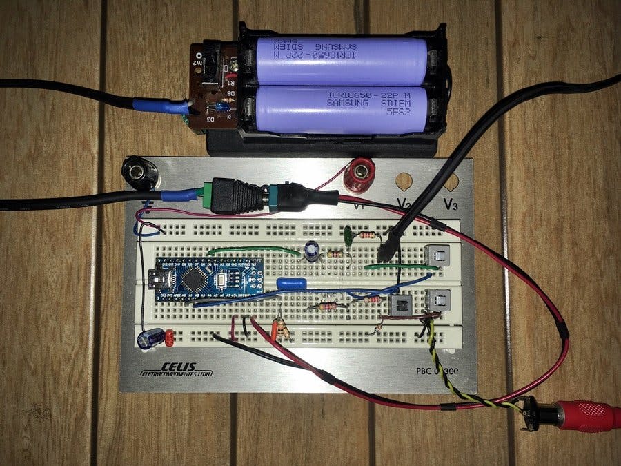
Picture of setup:
How it works:The operation is analogous to the bucket brigade (BBD) principle used by the famous MN3005 integrated circuit, used in the classic analog pedals of the 70s and 80s.
The audio signal coming from a source, such as a tablet, cell phone, mp3 player, keyboard, mixer, guitar amplifier, etc. goes to the input of circuit and filtered by a capacitor and then applied to the analog pin A0 - 10Bit A/D converter, where it is sampled and converted to bytes (values from 0 to 255). These bytes are stored in Arduino's SRAM memory, through a 1900 bytes buffer (array), which forms a delay line for the original signal.
When this buffer is full, the first byte that entered (and the subsequent bytes) that are stored in the buffer are sent to the 8Bit D/A converter. In reverse mode, the buffer is simply read backwards. The 8Bit D/A outputs the audio as PWM that is retrieved at pin D5 of the Arduino where is filtered by a capacitor and the reconstructed audio is ready to go to the output of circuit.
To improve the audio quality, I set the PWM frequency to ~64kHz and Timer 1 to ~16kHz, so we have a pratical sampling rate of ~6.3kHz.
A part of the output signal is applied to the input, creating a feedback, which is responsible for the echo repetitions. The output audio signal must be sent to the line input of an audio amplifier to be heard.
The Arduino status LED lights up to indicate when the push button is pressed and the TX LED lights up to indicate it is in reverse speech mode.
Schematics / Wiring:
Instructions:- Open the sketch in the Arduino IDE, connect the Arduino, set the correct port.
- Compile the sketch and send it to Arduino.
- Make the circuit assembly following the schematic diagram to make the electrical connections.
Operation:- Power the Arduino through the USB port or through a 7 to 9v battery connected to the vin pin.
- Connect the audio source to the audio input and the output to an audio amplifier, which can be a PC sound amplifier.
- Press to turn on switches SW2 and SW3.
- Press the S1 push button sequentially to select the 6 delay times plus the Reverse Speech mode. The delay time values available are: 63ms, 110ms, 158ms, 205ms, 253ms, 300ms and Reverse Speech. The Arduino status LED lights up to indicate when the push button is pressed and the TX LED lights up to indicate it is in reverse speech mode.
- Press to turn off the SW3 switch to freeze the sound. Then press it again to return.
- Press to turn off switch SW2 to cut the feedback, that way we will only have the processed signal (wet) to obtain the LO-FI sound of 8Bit, Bitcrusher and reverse speech.
Possible improvements for use with guitars:For pratical use with guitar it is necessary to implement an active pre-amplifier with operational amp (such as the TL072), one in the input and other in the output of this circuit, to match the high impedace of this simple circuit.
By J. CesarSound - ver 1.0 - Jan / 2021.


Comments