
Hardware components | ||||||
| × | 1 | ||||
 |
| × | 1 | |||
 |
| × | 1 | |||
 |
| × | 1 | |||
 |
| × | 1 | |||
 |
| × | 1 | |||
 |
| × | 1 | |||
 |
| × | 1 | |||
Software apps and online services | ||||||
 |
| |||||
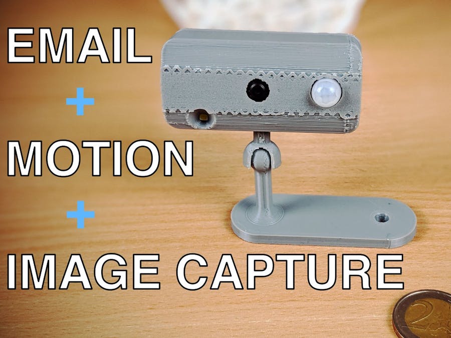
We build upon the previous ESP32-CAM projects and build a motion-triggered image capturing system that also sends an email with the image as an attachment. This build uses the ESP32-CAM board along with a PIR sensor module that is based on the AM312 sensor. The board spends most of the time in sleep mode and wakes up to take an image once motion is detected. In part 1, we modify the previous time-lapse sketch to add the motion detection feature. We then update the sketch and add the email feature in part 2.
The video above covers everything you need to know and also explains how the sketch is put together.
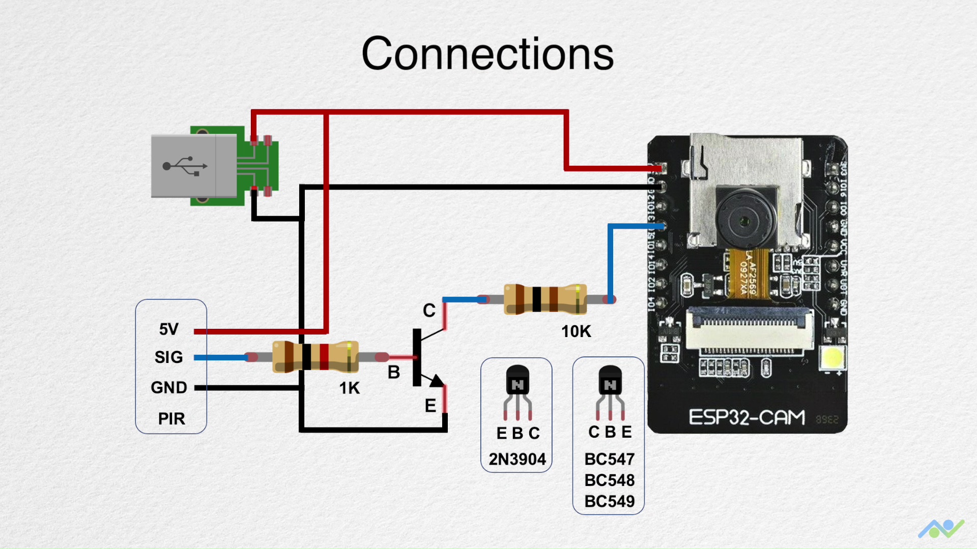
Step 1: Gather the ElectronicsThe ESP32-CAM board already contains the camera module, and microSD card slot that we need for this sketch. In addition to this, you will need a microSD card, a PIR sensor module (based on the AM312 sensor), a general-purpose NPN transistor (BC547, BC548, BC549 or 2N3904), a microUSB breakout board, a 10K Ohm and 1K ohm resistor and also a USB to serial converter to upload the sketch.
Step 2: Upload the Sketch for Part 1The ESP32-CAM board does not have an onboard USB connector so you need to use an external USB to serial converter to upload the sketch. You can use the wiring connections shown above but make sure that the USB to serial converter is connected in the 3.3V mode.
It is recommended to use an external 5V supply to power the board, particularly if you are using an FTDI breakout board. For the external 5V supply, a simple USB breakout board will do just fine. There has been some success in powering the board directly from the CP2102 breakout board so you can try that first. The board also has a 3.3Vpower pin if needed.
The jumper is needed to put the board in the download mode. Once you have everything connected, power up the board, open a serial terminal (Tools->Serial Monitor) with a baud rate of 115, 200 and press the reset button. You should obtain an output as shown in the image and this will indicate that everything is working as expected.
You can download the sketch using the link at the bottom of this post.
Step 3: Connect the Circuit and TestBuild the circuit using a breadboard and test to make sure everything works as expected. I added a multimeter to the final sensor output to help determine its state. Once you're happy with the way everything works, move on to part 2.
Step 4: Install the Mail Client LibraryOpen up the library manager and type in "ESP32 Mail Client". Install the library that shows up as we need this for the sketch.
Step 5: Upload the Sketch for Part 2Download the sketch using the link at the bottom of this post.
Open it up using the Arduino IDE and then update it with your details. You will need to add the network name and password as the board needs to connect to the WiFI network. You will also need to provide an email address along with the password for the board to send the email. I'd recommend creating a new GMAIL account. Once the account is created, you need to enable less secure apps by visiting the following link:
https://myaccount.google.com/lesssecureapps?pli=1You also need to specify the recipient and you can have multiple if required. Watch the video to learn more. Once all of this is done, upload the sketch to the board and power it ON. I'd recommend connecting the serial terminal and watching the output as this will notify you if there are any errors.
If everything works as expected, then the board should capture, save an image and also send it across as an email.
Step 6: Add the Electronics to an EnclosureI used the enclosure from the following link: https://www.thingiverse.com/thing:3667886
I added supports and printed it face down, which didn't give a very good finish but this should work for now. Since the PIR sensor was a little too big for the enclosure, I desoldered the sensor and connected it to the PCB using wires. I then created the interfacing circuit using a protoboard and wired it in place. Use the connection diagram shown earlier to connect it all together and you can add some Kapton tape for insulation.
I started by glueing in the PIR sensor, followed by the PIR PCB. I then placed the ESP32 board inside and realised that the case doesn't allow you to access the microSD card but this didn't matter to me as the images would be emailed. I then added the interface board and glued in the microUSB breakout board. Finally, I bent the transistor to allow the cover to close in place. Power on the board and it should take an image when motion is detected.
Here are some relevant links in case you would like to learn more about us. Thank you for your support!
- YouTube: https://www.youtube.com/channel/UCbWiK1A5RqAugSquBHuyBdA
- BnBe Website: https://www.bitsnblobs.com/
- Instagram: https://www.instagram.com/bnbe.club/
- Facebook: https://www.facebook.com/BnBe.club
- Twitter: https://twitter.com/bnbe_club
Comments