

Hardware components | ||||||
| × | 9 | ||||
 |
| × | 9 | |||
 |
| × | 2 | |||
Software apps and online services | ||||||
 |
| |||||
As the holidays approached this year, I felt a need to create a DIY gift for my family and friends. I struggled at first to find a medium. Should I 3D print something? Should I knit? But then it hit me: everyone loves blinky LEDs and I want to keep getting better at PCB design. I'll do a PCB ornament!
ConceptThis of course is not an original idea. Many have created a PCB ornament or other holiday-themed blinky board; especially as badge life continues to become somewhat of a religion among the maker set. I wanted mine to be pretty basic since I wanted to make *a lot* of them and wanted to do minimal troubleshooting with December fast approaching and how quickly fabrication and shipping times can add and multiple.
At first I considered a PWM-based 555 timer circuit. But, I wanted this project to last for a decent amount of time on a 2032 coin cell battery since they were going to be gifts to people who may not be electronically minded. And, I worried about current demands, voltage needs and, although less important in a practical sense: board aesthetics. I wanted the front of the board to be incredibly clean and everything else to live on the back. Considering an ornament should be fairly small in diameter and a 2032 battery holder being fairly large in size the restraints were adding up.
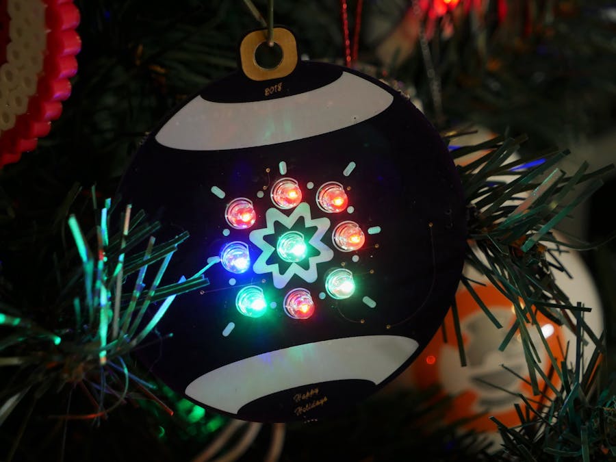
Proof of ConceptThis led me to a fun component choice: slow-flashing RGB LEDs. I first used these when I assembled the super festive Xmas Tree Hat for the Raspberry Pi by Pi Hut. I used the 3mm version to fit the footprint and this allowed me to run a very simple script to just have the LEDs receive power and change colors on their own in the full Roy G. Biv spectrum.
Basically these LEDs look the same as a traditional LED: they have just a cathode and an anode unlike traditional RGB LEDs that have 5 leads. When the slow-flashing RGB LEDs receive power they slowly shift between individual red, green and blue filaments that are inside the LED thanks to an embedded chip. Each LED will have slightly different timings for changing colors and it also varies throughout the time that it's powered on, so eventually you have this fun rotating kaleidoscope of colors with minimal effort.
I wasn't sure what the best resistor and battery combination would be for these LEDs though long term. Sure, initial power with a 220 ohm resistor and a 2032 battery looks great, but would it still look great in an hour? How about four hours? I hooked up nine of these LEDs on a breadboard to test different resistor values over time with a 2032 battery. I eventually settled on 1K ohm with two 2032 batteries. Two batteries was a bit of a compromise to ensure that the longest and most effective lifespan could be achieved. If you're interested in going in-depth on slow-changing RGB LEDs and the results I found with different resistor values and battery combinations you can check out this video I made here.
Make the PCB PrettyOnce I had my circuit figured out, I started planning out the art for the PCB. This was the first time I was attempting this so I knew I wanted it to be simple yet effective. I decided on a circular shape overall with a rounded square at the top to resemble the hook area that you often find at the top of a bauble. For the rest of the design I drew in two vector shapes and then used text for the date, "Happy Holidays" and even the star-esque design in the middle; which is actually a Unicode character.
To create PCB art, you basically export different portions of your vector image and then import them into your PCB design software so that they'll exist in different layers of the PCB, which them gives you the different effects. For example, if you were to export a simple cartoon image you might have the shadows and outline show-up on the silkscreen layer and then for the rest of the cartoon you might have it so that no silkscreen is present to show the bare copper.
There's a great video by Andrew Sowa that he did with Hackster (meta) where he goes thru the process of exporting your different art layers from Illustrator. I found that following along with this makes things super easy to understand.
To the Software!Once you have your image layers exported you have to get them into your PCB software. In the video above, Andrew goes on to import into KiCad. At the moment I'm using Eagle and decided to convert my images into bitmaps since this seemed like the easiest and least painful process although it isn't without its own issues (there really isn't a method doesn't have at least one issue). Basically to do this I opened my images with MS Paint and then saved it as a Monochrome bitmap file.
After gathering all the bitmaps, I went into Eagle with a fresh board file. You bring in bitmaps by going to File - Import - Bitmap. You'll be brought to a menu and if scaling matters to you (I'm going to go out on a limb and say it does) then you'll want to select DPI as your import and then enter the scaling that you used in your Illustrator export if you were following along with Andrew's video. Once all of your info is correct run the script and you should see your art slowly appear line by line in Eagle.
An important note though: you'll want to import one bitmap and then adjust it's layer distinction, otherwise it's basically impossible to do. So after your first bitmap is imported go on to the next step before importing any others.
LayersAfter your bitmap image is imported, you'll want to make sure it's assigned to the correct layer to get your desired PCB effect. Do this by highlighting your bitmap and then selecting the Change tool in the side menu. This brings up an additional menu where you'll select Layer. This then brings you to the next menu in this rabbit hole where all of the layers of the PCB are listed. Select your desired layer, press okay and then right-click your highlighted bitmap and click on Change Group. You should see your bitmap change color to reflect the layer change.
As you follow these steps with your subsequent layers, I found it helpful to import a new bitmap, make sure it's lining up correctly with your previous bitmaps, hide the previously imported bitmaps' layers and then go thru the layer change step. This makes it so that you don't get confused on what layer and bitmap you're working with.
Oh yeah the circuit...After all the bitmapping it feels like the project should be done but now it's time for really the only part that actually matters: the circuit. Go to your schematic view, choose your components and connect everything up. After this your footprints will import into the board view with your art and you'll be able to place and route your components as normal.
An important note on routing: you'll want to make sure that your routing doesn't cross paths with any bitmap layers that are rocking copper since this will cause shorts and other undesirable effects (unless it's done purposefully).
Then check, double check and triple check your board and then make peace with the fact that you will probably still have some sort of mistake after they get back from fab that is your own doing. Then send them off and wait patiently by the mailbox.
Assembly and Final ThoughtsBack to my board, I was pleasantly surprised on how they came out. The art was exactly as I envisioned it and the footprints for all of my components were correct. However, I did miss a trace for LED4 and have had to utilize a bodged bent anode to connect the LED to it's accompanying resistor.
I think what helped in keeping the PCB carnage and bodging to a minimum was that I kept both the art and the circuit simple to try and eliminate variables that could lead to failure. You can always create more complicated designs later but this will be delayed if you're spending a lot of time troubleshooting your original first design that was maybe overreaching just a bit.
If you don't have a traditional electronics background PCB design can seem scary, overwhelming and something that's meant for more experienced people that have "real skills". If you start simple and slowly add-in new methods and design features to your boards you'll soon realize it isn't so scary and that much like everything else in life it just takes practice and patience to learn. And once you have your first project on a custom PCB instead of a piece of perf board you'll be hooked.

_t9PF3orMPd.png?auto=compress%2Cformat&w=40&h=40&fit=fillmax&bg=fff&dpr=2)


Comments